| This documentation is out of date.
The new version of the documentation is here: https://cannylogic.com/docs |
CANNY 5.2 duo
Contents
General Information
As well as CANNY 7 controllers CANNY 5.2 duo may be attributed to a class of smart relays or Nano PLC.
In contrast to the CANNY 7, controller CANNY 5.2 duo has two CAN interfaces.
Three channels of controller may be operating in the output mode and the input mode, one channel may operate in the analog-digital converter (ADC).
A feature CANNY 5.2 duo is support USB interface, which allows upload user programs to the controller without using a special programmer - is enough to have only the adapter cable USB-A - miniUSB, and support for UART interface to the USB interface (USB Virtual COM- port) allows you to share data with other devices such as PCs, during the execution of a custom function diagram.
The principal characteristics CANNY 5.2 duo include:
- rated power supply and IO channels voltage 0 / 12V (18V max);
- the maximum output current of each of the 3 IO channels +/- 100mA, sufficient to control usual automotive relay;
- two CAN 2.0B Interface, compliant with ISO-11898, SAE J2411 widely used in modern cars;
- one ADC, over one of the input-output channel;
- one UART interface via USB Virtual COM-port;
- built-in energy consumption management in the range of 4 to 30 mA, helps to conserve battery power during period of inactivity in a car;
- EEPROM for applications and sixty-four 16-bit non-volatile memory data cells, available to user application to preserve critical data during a power failure;
- wide operating temperature ranged from -40° to + 85° C;
- compact housing compliant to IP50 enclosure protection specification, suitable for installation and operation as part of a car cabin equipment.
To develop custom software for CANNY 5.2 duo, use graphical programming language CFD to quickly create user-effective applications- Functional Diagrams. The free of charge IDE CannyLab contains tools for editing, debugging and writing software to the controller.
Requirements for writing software to the controller:
- PC with a USB port version 1.1 or higher
- Installed CannyLab IDE
- Ordinary miniUSB cable
Controllers' memory accessible to user is enough to accommodate the program, consisting of several hundred functional blocks, which allows for fairly sophisticated algorithms. Two-coloured LEDs, controlled from the user application, are useful to indicate controller or debugging mode.
Design and functional operation
The appearance and layout
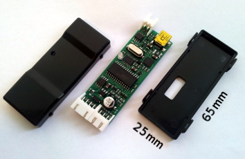
The main components of CANNY 5.2 duo are: a micro controller (MCU) with the auxiliary circuits, power supply system for all controllers' elements, IO channels level matching circuit, electric protection system, connectors and LED, based on a single print board 65 x 23 mm mounted inside a quick-open plastic casing. The controller has three external connectors and one internal. To connect the controller to the power supply and external devices, the kit includes a set of jumper harness.
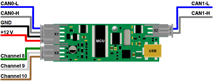
- External connector X1 contains four terminals: + 12V input, power input GND, CAN0-H and CAN0-L.
- External connector X2 contains two terminals: CAN1-H and CAN1-L.
- External connector X3 has three terminals, channels accordingly- №8, №9 and №10. Internal connector USB is to connect controller to the PC with miniUSB cable. Also, USB connector may be used to exchange data with the PC during execution of the user diagram through USB Virtual COM-port.
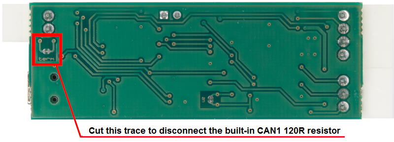
By default, on the controller board, between the CAN1-H and CAN1-L lines, a terminating resistance is set.
If necessary, this resistance can be disconnected by breaking the “term” jumper located on the back side of the board near the X2 connector. You can restore a broken jumper using special pads.
Software Architecture
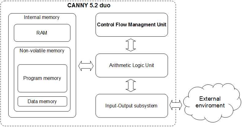
CANNY 5.2 duo is a digital programmable computing control device. CANNY 5.2 duo main structural elements are: arithmetic logic unit (ALU), internal memory, commands execution management subsystem and input-output system.
Arithmetic Logic Unit is the processing core of CANNY 5.2 duo. ALU provides system software and user functional execution diagram placed into the internal memory of the controller. Controller's internal memory is divided into the EEP program memory, EEP data memory, and ROM. The command's management subsystem is responsible for switching and setting mode of the controller. The IO system provides controllers' communication to the outside world, using both discrete IO channels and standard digital interfaces CAN / UART / USB.
Software Structure
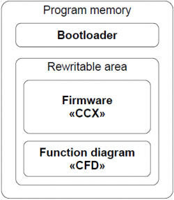
Software CANNY 5.2 duo consists of: a bootloader, system software (operating system and drivers), and a custom function diagram.
The bootloader provides the controller with the software download mode, organising data transmission between CANNY 5.2 duo and PC. It checks the data integrity transmitted from the PC and loading to the controllers' internal memory. The bootloader placed into the internal memory of the controller during production and can not be deleted or modified by the user. The manufacturer distributes CANNY 5.2 duo firmware in CCX file format. It includes an operating system and a set of drivers providing function diagram execution and its interaction with the controllers' resources. The contents of various CCX files can be reloaded into the controller by user but user is restricted to modify CCX file content.
Custom block diagram is created and modified in CannyLab IDE, then it can be loaded into the controller where it specifies the algorithm to work standalone or saved in to CFD file.
Operation modes
There are several operation modes to perform basic operations with controller.
Software upload mode
In this mode, the controller is running bootloader to load firmware, and functional diagram under CannyLab management. Controller switch to this mode automatically when connected to PC. More information in chart General Information
To move the controller in this mode, you must connect it to a PC via USB-A-miniUSB-cable adapter, with the embedded controller is activated the green LED, and connect the device to a PC, the LED will stay on.
Exit from this mode happens automatically when the connection to the PC is disrupted. At the end of the software download mode, if EEPROM system software is loaded correctly, the controller will switch to running mode, otherwise it returns to SW download mode.
Running mode
Running mode is the main controllers' mode. In this mode, the controller is running continuously under system software sequence, in an endless cycle, performing the functional diagram, working on the algorithm specified by the user.
Transition to this mode takes place automatically when the controller is connected to an external 12V power supply.
When operating in this mode, the functional diagram has access to all resources of the controller and drivers included in the controllers' system software.
Sleep mode
This mode is an option of normal running mode in which, after each cycle of execution of a function diagram, the controller pauses to reduce its power consumption to a minimum. Thus, the controller operates in a pulsed mode, periodically "asleep" and "waking up". Enable, disable, and configure the parameters of this mode are controlled by the functional diagram. Using this mode is relevant when developing systems, focused on battery-power, such as the on-board car equipment.
Runtime Environment
Functional diagram presentation
The graphical block diagram developed in CannyLab environment, automatically processed by the translator just before loading to the controller. CannyLab checks on the consistency of the diagram, determines function blocks execution order and converts the diagram into the executable code - a sequence of machine instructions CANNY 7 controllers' ALU.
The execution order
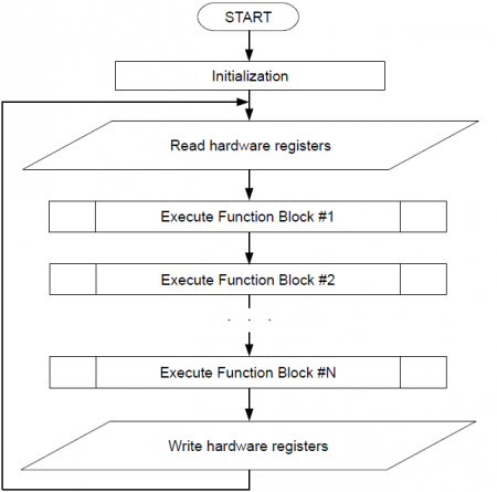
Executable program code during loading into the controller already contained system software, is including in the sequence of the system software machine instructions. Thus, the aggregate command sequence loaded with system software and functional diagram, will be: initialisation routines executed once after each controllers' reset and executable functional diagram code, framed with the controller resources' procedure management, and placed in an infinite executable loop - diagrams running loop. Some of the drivers included in the controller system software, such as CAN driver, require controller to raise immediate response during data transmission and reception of program events. Program code of these drivers asynchronously processed by the controller in parallel with the main execution flow. In the processing of asynchronous drivers calls, the diagrams main run loop performance is briefly suspended.
Access to hardware resources
All available resources to the user from the functional diagram : the system resources of the controller, IO subsystem and additional drivers included in the system software, appears on a controllers' internal memory protected address space. This address space is divided into read-only registers and write-only registers.
The user is able to specify the read-only register address as a source of input data from virtually any function block of a diagram. Thereby extract and use to implement their own algorithms, data received by the controller from the outside world. For example information about the electric potential on any controllers' terminal, or the data packet contents received from the CAN bus. Write-only register address can be used as the output target for any functional block on the diagram. Thus, the user controls the resources of the controller from functional diagrams which gives an opportunity to influence the objects of the outside world. For example: switch external relay by changing the electrical potential on one of the pins of the controller, turn LED on; set CAN operation mode; send a data packet.
The most resources used include assignment required operating parameters, such as the CAN communication speed and so on.
Specifying these parameters is made in the form of recording specific constants in one or a few specific registers, depending on a required set of resources configuration. For example, the transfer constant of value 1 in the register, located at 1027 sets CAN0 driver settings for bus operation to 125kBod speed.
In CannyLab IDE, for user convenience, all the of the controllers' available registers are named, as well as all special constants that are used in interaction with the controllers' resources. Therefore, the operation for the user CannyLab looks like setting a constant named "CAN 125" to register the name "CAN0 Mode Setup Register».
Similarly, the appearance of the value "1" in the registry located at 1184 ("DIO Input Value, IO Channel 8"), we can learn about the application of a negative electric potential to the pin 1 connector X3 of controller.
