| This documentation is out of date.
The new version of the documentation is here: https://cannylogic.com/docs |
Difference between revisions of "PWM Generator"
| [unchecked revision] | [unchecked revision] |
| Line 44: | Line 44: | ||
<div> | <div> | ||
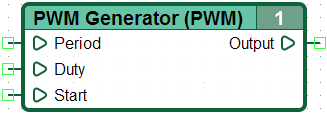
| − | + | At non-zero value at the input "Start", generates а logic one at the output with a predetermined duration and periodicity. | |
[[File:5_8_3_3.png|left|thumb|Pulse signal parameters]] | [[File:5_8_3_3.png|left|thumb|Pulse signal parameters]] | ||
| Line 54: | Line 54: | ||
== Features == | == Features == | ||
| − | + | When working with CANNY 7, it is a good practice to use the time intervals greater than 5-10 ms. | |
| − | + | When specifying temporal values on the diagram, it is necessary to take into account the duration of the diagram execution cycle, which depends on the model of the controller, the size of the chart, controllers' operation mode, controller periphery. It may be varied from cycle to cycle within certain limits during operation. Exact execution time for each cycle is available in the register, during controller operation [[System Registers#Фактическое время выполнения функциональной диаграммы | "Длительность программного цикла"]]. | |
| − | + | Time intervals in the diagram should not be specified by value less than the duration of one cycle and will be measured with an uncertainty about the duration of one cycle of a user diagram. | |
| − | == | + | |
| + | == Examples == | ||
{| | {| | ||
|- | |- | ||
Revision as of 09:04, 26 November 2015
| Appearance | |
|---|---|

| |
| Symbol | |
| PWM | |
| Group | |
| Timers and Generators | |
| Inputs | |
| Period, мс: | Integer |
| Duty, мс: | Integer |
| Startт: | Logical |
| Outputs | |
| Выход: | Logical |
| Version CANNY Lab | |
| from 0.6b | |
For asynchronous generation of the precision PWM signal at the output using Драйвер каналов ввода-вывода or Драйвер ВЧ ШИМ
Features
When working with CANNY 7, it is a good practice to use the time intervals greater than 5-10 ms.
When specifying temporal values on the diagram, it is necessary to take into account the duration of the diagram execution cycle, which depends on the model of the controller, the size of the chart, controllers' operation mode, controller periphery. It may be varied from cycle to cycle within certain limits during operation. Exact execution time for each cycle is available in the register, during controller operation "Длительность программного цикла".
Time intervals in the diagram should not be specified by value less than the duration of one cycle and will be measured with an uncertainty about the duration of one cycle of a user diagram.


