Genegal Description
CANNY 5.2 duo users have access to three discrete general purpose IO channels. Each channel is physically available through corresponding pins of X3 connectors. Writing and reading data of the respective drivers registers, the functional diagram can manage the electric potential in each of these contacts and getting information about the current potential of each of them. The channel physical characteristics allow connection to various external low-voltage control circuit, or using an external protection diode, small electromagnetic relays. As an external digital signal controller capable of managing the work may use mechanical, electromechanical, and electronic buttons and switches, pulse generators, sources 0-12V voltage, the transistor outputs of various equipment, etc.
Channels operation mode and parameters specified by function diagram. At any given time, the channel can only work in one of the possible modes, but it is possible to dynamically override the channel configuration from the functional diagram.
| ATTENTION!
|
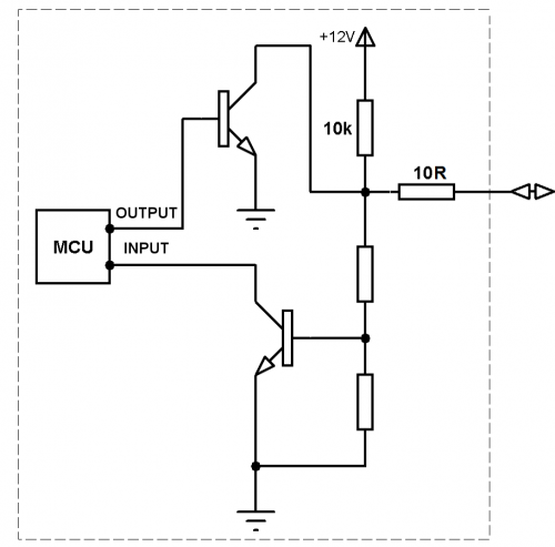
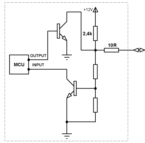
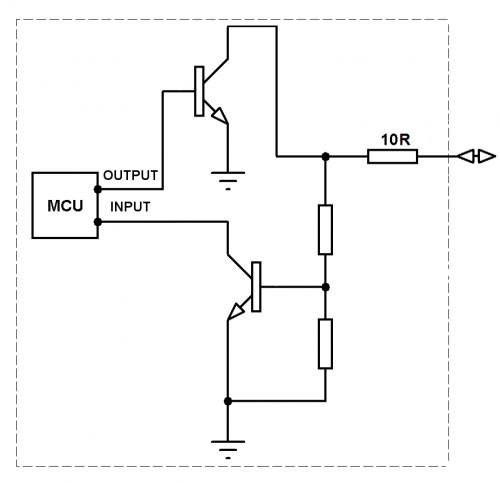
Unlike CANNY 7 channels CANNY 5.2 duo are not have intellectual protection against short-circuit or overload. channel circuits are protected by a current-limiting resistors combustible (see. circuit diagram). To avoid output channels down, avoid direct connection channels with the included output potential GND to the power circuits of positive polarity!
|
IO Registers
The parameters defining operation mode and channel current state, are set for each channel independently. Below is acceptable values specifications of registers controlling input-output channels operation in all major modes.
| Register
|
Expected values
|
| DIO Output Value Register, IO Cannel 8
|
| DIO Output Value Register, IO Cannel 9
|
| DIO Output Value Register, IO Cannel 10
|
|
|
|
|
In Digital Input mode:
|
| 0...65535
|
=
|
the value is ignored;
|
|
|
|
In Digital Output mode:
|
| ≥ 1
|
=
|
set at the appropriate controller pin, the electric potential specified by this channel configuration for status "ON";
|
| 0
|
=
|
set at the appropriate controller pin, the electric potential specified by this channel configuration for status «OFF»;
|
|
| DIO Input Active Wait / Raising Edges Counter Enable Register, IO Channel 8
|
| DIO Input Active Wait / Raising Edges Counter Enable Register, IO Channel 9
|
| DIO Input Active Wait / Raising Edges Counter Enable Register, IO Channel 10
|
|
|
|
|
In Digital Output mode:
|
| 0...65535
|
=
|
the value is ignored;
|
|
|
|
In Digital Input mode:
|
| ≥ 1
|
=
|
set the appropriate controller pin to the active mode / turn on counter mode - react to potential changes to the respective contact controller / to count the number of potential changes from the state "OFF" to state "ON";
|
| 0
|
=
|
set the appropriate controller pin to normal mode of operation as a digital input.
|
|
Registers control IO channels driver are divided into containing information of the IO driver altogether and containing information about the state of each channel individually. The following describes registers control driver return values of IO channels in all major operation modes.
| Register
|
Return values
|
| DIO Input Activity Detect Register
|
| 1
|
=
|
during the last execution cycle of a functional diagram, registered the change of the electric potential in any controller pin respective to a channel which is configured as an active input or pulse counter; or register values of output channels either input-counters were changed by a diagram;
|
| 0
|
=
|
for the last functional diagram execution cycle, changes on active controller inputs or changes in the values of drivers' registers is not found.
|
|
| DIO Input Valve Register, IO Channel 8
|
| DIO Input Valve Register, IO Channel 9
|
| DIO Input Valve Register, IO Channel 10
|
|
|
|
|
In Digital Input or Output mode:
|
| 1
|
=
|
at the appropriate controller pin established electric potential corresponding to the polarity of the channel in the "ON" mode;
|
| 0
|
=
|
at the appropriate controller pin established electric potential corresponding to the polarity of the channel in the "OFF" mode;
|
|
| DIO Input Counter Valve, IO Channel 8
|
| DIO Input Counter Valve, IO Channel 9
|
| DIO Input Counter Valve, IO Channel 10
|
|
|
|
|
In Input Counter mode:
|
| 0...65535
|
=
|
the number of pulses registered in the appropriate controller pin after activation counter mode;
|
|
|
|
In Other mode:
|
| 0
|
=
|
always 0.
|
|
Channel neutral state
При включении контроллера, все силовые выходные элементы каналов находятся в выключенном состоянии. На контактах контроллера соответствующих каналам 8 и 9 устанавливаются потенциал 12В/1мА на контакте соответствующем каналу 10 — очень слабый отрицательный потенциал («воздух»).
Работа с каналами из пользовательской диаграммы
При записи ненулевого значения в регистр выходного значения канала на соответствующем контакте контроллера установится электрический потенциал «GND» 120мА, а при записи значения «0», потенциал соответствующий состоянию канала в момент запуска контроллера (см.выше).
| Примечание:
|
В любой момент времени, вне зависимости от состояния выхода канала возможно получить значение, соответствующее фактическому текущему электрическому потенциалу на контакте данного канала, что позволяет организовать обратную связь и, при необходимости, реализовать программную защиту от перегрузки канала.
|
An example of a functional diagram performing every second, alternate switching of electrical potentials from + 12V (1mA) to GND (120 mA) at controller terminals, corresponding to channels #8 & #9.

| ATTENTION!
|
Unlike CANNY 7 channels CANNY 5.2 duo are not have intellectual protection against short-circuit or overload. channel circuits are protected by a current-limiting resistors combustible (see. circuit diagram). To avoid output channels down, avoid direct connection channels with the included output potential GND to the power circuits of positive polarity or организуйте программную защиту канала в диаграмме!
|
The channel returns a value of "1" in its input value register, if on the appropriate controller pin establishes an electrical potential "GND"; and returns the value "0" to input value register, if on the appropriate controller pin establishes an electrical potential "+ 12 V".
Change potential on the channel pin #8 & #9, will result in immediate automatic exip controller from hibernation.
Каналы контроллера в режиме дискретного входа работают с максимальной чувствительностью, т.е. «защита от дребезга» не предусмотрена и должна быть реализована, при необходимости, в функциональной диаграмме.
An example of a functional diagram, switching-on a built-in green LED with the flow and hold for at least 200ms at the appropriate pin of channel №8, the potential GND:

Equivalent circuit diagrams
Equivalent circuit diagrams for each possible state of the input-output channel shown in the table below:
| Channel of controller
|
Equivalent circuit diagram
|
| Channel #8
|
|
| Channel #9
|
|
| Channel #10
|
|
See also
CANNY 5.2 duo


