| This documentation is out of date.
The new version of the documentation is here: https://cannylogic.com/docs |
CANNY Lab Main window
CannyLab user interface consists of a single window - the main program window.
Contents
Main window
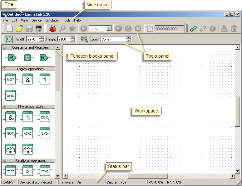
The main window is divided into several areas:
- window title;
- main menu;
- toolbar;
- function blocks panel;
- workspace;
- status bar.
Depending on the current operating mode of the editor, some of CannyLab menu items and panels may not be available or hidden.
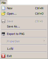
Menu "File" contains commands to work with CannyLab files.
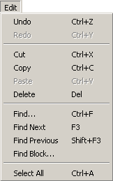
Menu "Edit" contains editor appearance adjustment commands.
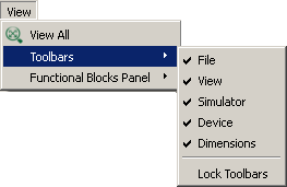
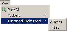
Menu "View" contains toolbar view customization and function block panel representation.
|
|
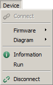
Menu "Device" contains commands to work with the controller.
| - load firmware to the controller; | |
| - erase controller firmware; | |
| - load user's functional diagram; | |
| - erase user's functional diagram. |
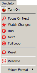
Menu "Simulation" contains controller software emulation mode control commands in the CannyLab environment.

|
- setting decimal number system; |
| - setting hexadecimal system; | |
| - setting binary system; | |
| - setting character data mapping. |
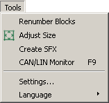
Menu "Service" includes service commands and CannyLab settings.
|
|
| - reorder functional blocks numbers on the diagram; | |
| - creation of autonomous firmware flash file; | |
| - start CAN-monitor; | |
| - change CannyLab settings; | |
| - CannyLab interface language selection. |
Menu "Help" provides links to this guide and information about the program.
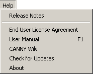
|
|
| - View CannyLab program changes history file; | |
| - open CannyLab reference guide; | |
| - get information about program current version. |
Toolbars
Toolbars allows to access the most popular commands of CannyLab.
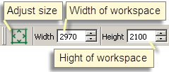
Desktop Control Panel allows to scale the image to the workspace and change its dimensions in pixels. To quickly zoom in/out, rotate the mouse wheel while holding down the button «Ctrl» keyboard.
Workspace
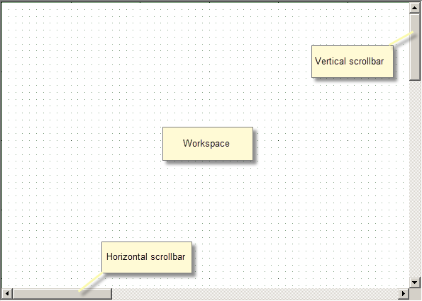
Workspace is designed to display, edit, and debug functional diagrams. The background of the workspace is a grid that facilitates the positioning of functional diagram elements. To move over the diagram displayed in the workspace used the vertical and horizontal scroll bar, mouse wheel or arrow keys.
Строка состояния
В строке состояния отображаются: для какого типа контроллера предназначена текущая функциональная диаграмма, наличие связи с контроллером, наличие в подключенном контроллере системного программного обеспечения и пользовательской диаграммы. Кроме того, в режиме симуляции в строке состояния отображаются сведения об использованных пользовательской диаграммой ресурсах контроллера.
Панель функциональных блоков
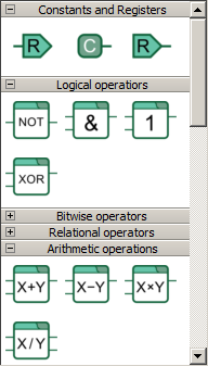
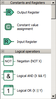
Панель функциональных блоков содержит все доступные для использования при построении функциональных диаграмм типы блоков. Функциональные блоки в данной панели объединены в группы по назначению и, в зависимости от настроек отображения, могут быть представлены в виде значков или списка. Прокрутку панели функциональных блоков можно выполнить при помощи вертикальной полосы прокрутки или колеса мыши.
Два варианта отображения панели функциональных блоков:
|
|
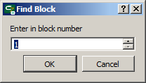
Диалог поиска функционального блока по его порядковому номеру
Доступ к диалогу поиска функционального блока по его порядковому номеру CannyLab можно получить, выбрав пункт «Правка» → «Найти блок» главного меню программы.
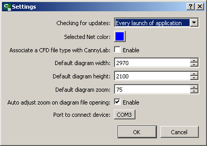
Диалог настройки параметров
Доступ к диалогу настройки параметров CannyLab можно получить, выбрав пункт «Сервис» → «Параметры» главного меню программы.
Список горячих клавиш
| F1 | Открыть справочное руководство; |
| Ctrl+N | Создать новый файл диаграммы; |
| Ctrl+O | Открыть файл диаграммы; |
| Ctrl+S | Сохранить файл диаграммы; |
| Ctrl+A | Выделить все; |
| Ctrl+Z | Отмена последнего действия при создании и редактировании диаграммы; |
| Ctrl+Y | Возврат последнего отмененного действия при создании и редактировании диаграммы; |
| Del | Удаление выделенных элементов диаграммы; |
| Esc | Выход из режима редактирования сети; |
| ←, ↑, →, ↓ | Сдвиг экрана отображения рабочей области влево, вверх, вправо, вниз; |
| PageUp, PageDown | Сдвиг экрана отображения рабочей области на страницу вверх, вниз; |
| Ctrl + колесо мыши | Быстрое изменение масштаба отображения рабочей области; |
| Alt + колесо мыши | Горизонтальная прокрутка рабочей области редактора; |
| Shift + колесо мыши | Ускоренная вертикальная прокрутка рабочей области редактора; |
| Нажатое колесо + движение мыши | Перемещение поля диаграммы внутри рабочей области («перетаскивание»). |
