| This documentation is out of date.
The new version of the documentation is here: https://cannylogic.com/docs |
Difference between revisions of "CANNY Lab Main window"
| [unchecked revision] | [unchecked revision] |
(→Keyboard shortcuts) |
(Initial edit, readability rewrites.) |
||
| Line 17: | Line 17: | ||
=== Main menu === | === Main menu === | ||
| − | Menu "File" contains commands | + | Menu "File" contains commands for working with CannyLab files. |
{| | {| | ||
| Line 24: | Line 24: | ||
| | | | ||
|- style="padding:0px;line-height:0.8;" | |- style="padding:0px;line-height:0.8;" | ||
| − | | ''- create a new | + | | ''- create a new function diagram file;'' |
|- style="padding:0px;line-height:0.8;" | |- style="padding:0px;line-height:0.8;" | ||
| − | | ''- open existing | + | | ''- open an existing function diagram file;'' |
|- style="padding:0px;line-height:0.8;" | |- style="padding:0px;line-height:0.8;" | ||
| − | | ''- save current | + | | ''- save the current function diagram file;'' |
|- style="padding:0px;line-height:0.8;" | |- style="padding:0px;line-height:0.8;" | ||
| − | | ''- save current | + | | ''- save the current function diagram file under a new name;'' |
|- style="padding:0px;line-height:0.8;" | |- style="padding:0px;line-height:0.8;" | ||
| − | | ''- save screenshot of the | + | | ''- save a screenshot of the function diagram in the PNG graphic format;'' |
|- style="padding:0px;line-height:0.8;" | |- style="padding:0px;line-height:0.8;" | ||
| ''- view the current file properties;'' | | ''- view the current file properties;'' | ||
| Line 42: | Line 42: | ||
| − | Menu "Edit" contains | + | Menu "Edit" contains the basic editing commands for working with the function diagram editor. |
{| | {| | ||
| Line 49: | Line 49: | ||
| | | | ||
|- style="padding:0px;line-height: 0.6;" | |- style="padding:0px;line-height: 0.6;" | ||
| − | | ''- undo the last action when | + | | ''- undo the last action when working with the diagram;'' |
|- style="padding:0px;line-height: 0.6;" | |- style="padding:0px;line-height: 0.6;" | ||
| − | | ''- | + | | ''- redo the last action when working with the diagram;'' |
|- style="padding:0px;line-height: 0.6;" | |- style="padding:0px;line-height: 0.6;" | ||
| − | | ''- cut the | + | | ''- cut the selected part of the diagram to the clipboard;'' |
|- style="padding:0px;line-height: 0.6;" | |- style="padding:0px;line-height: 0.6;" | ||
| − | | ''- copy the | + | | ''- copy the selected part of the diagram to the clipboard;'' |
|- style="padding:0px;line-height: 0.6;" | |- style="padding:0px;line-height: 0.6;" | ||
| − | | ''- paste part of the diagram contained in the clipboard;'' | + | | ''- paste a part of the diagram currently contained in the clipboard;'' |
|- style="padding:0px;line-height: 0.6;" | |- style="padding:0px;line-height: 0.6;" | ||
| ''- delete the selected part of the diagram;'' | | ''- delete the selected part of the diagram;'' | ||
| Line 67: | Line 67: | ||
| ''- search previous item by text;'' | | ''- search previous item by text;'' | ||
|- style="padding:0px;line-height: 0.6;" | |- style="padding:0px;line-height: 0.6;" | ||
| − | | ''- search function block by its | + | | ''- search function block by its ordinal number;'' |
|- style="padding:0px;line-height: 0.8;" | |- style="padding:0px;line-height: 0.8;" | ||
| − | | ''- | + | | ''- select of the entire diagram.'' |
|} | |} | ||
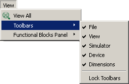
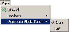
| − | Menu "View" contains toolbar | + | Menu "View" contains options for customizing the appearance of the toolbar, the function block panel, as well as an option for scaling the workspace. |
{| | {| | ||
| Line 82: | Line 82: | ||
| ''- scale the workspace by the contents of the diagram;'' | | ''- scale the workspace by the contents of the diagram;'' | ||
|- style="padding:0px;line-height: 0.8;" | |- style="padding:0px;line-height: 0.8;" | ||
| − | | ''- | + | | ''- toolbar appearance settings;'' |
|- style="padding:0px;line-height: 0.8;" | |- style="padding:0px;line-height: 0.8;" | ||
| − | | ''- | + | | ''- function block panel appearance settings.'' |
|} | |} | ||
| Line 93: | Line 93: | ||
| − | Menu "Device" contains commands | + | Menu "Device" contains commands for working with the controller. |
{| | {| | ||
| Line 102: | Line 102: | ||
| ''- search and establish communication with the controller connected via USB;'' | | ''- search and establish communication with the controller connected via USB;'' | ||
|- style="padding:0px;line-height: 0.8;" | |- style="padding:0px;line-height: 0.8;" | ||
| − | | ''- actions | + | | ''- actions for uploading and erasing the controller system software;'' |
|- style="padding:0px;line-height: 0.8;" | |- style="padding:0px;line-height: 0.8;" | ||
| − | | ''- | + | | ''- actions for uploading and erasing the function diagram;'' |
|- style="padding:0px;line-height: 0.8;" | |- style="padding:0px;line-height: 0.8;" | ||
| − | | ''- | + | | ''- information about the connected controller;'' |
|- style="padding:0px;line-height: 0.8;" | |- style="padding:0px;line-height: 0.8;" | ||
| − | | ''- space reserved | + | | ''- space reserved for use in future versions;'' |
|- style="padding:0px;line-height: 0.8;" | |- style="padding:0px;line-height: 0.8;" | ||
| − | | ''- | + | | ''- end the communication session with the controller;'' |
|} | |} | ||
| Line 116: | Line 116: | ||
|- style="padding:0px;line-height: 0.8;" | |- style="padding:0px;line-height: 0.8;" | ||
|rowspan="2" valign="top" style="padding-top:10px;"|[[File:4_4_1_6.png]] | |rowspan="2" valign="top" style="padding-top:10px;"|[[File:4_4_1_6.png]] | ||
| − | |style="padding-top:10px;"| ''- | + | |style="padding-top:10px;"| ''- upload firmware to the controller;'' |
|- style="padding:0px;line-height: 0.8;" | |- style="padding:0px;line-height: 0.8;" | ||
| ''- erase controller firmware;'' | | ''- erase controller firmware;'' | ||
|- style="padding:0px;line-height: 0.8;" | |- style="padding:0px;line-height: 0.8;" | ||
|rowspan="2" valign="top" style="padding-top:10px;"|[[File:4_4_1_7.png]] | |rowspan="2" valign="top" style="padding-top:10px;"|[[File:4_4_1_7.png]] | ||
| − | |style="padding-top:10px;"| ''- | + | |style="padding-top:10px;"| ''- upload the user's function diagram to the controller;'' |
|- style="padding:0px;line-height: 0.8;" | |- style="padding:0px;line-height: 0.8;" | ||
| − | | ''- erase user's | + | | ''- erase the user's function diagram from the controller.'' |
|} | |} | ||
| − | Menu "Simulation" contains controller software emulation mode | + | Menu "Simulation" contains controls for the controller software emulation mode in the CannyLab environment. |
{| | {| | ||
| Line 134: | Line 134: | ||
| | | | ||
|- style="padding:0px;line-height: 0.8;" | |- style="padding:0px;line-height: 0.8;" | ||
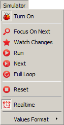
| − | | ''- enable/disable | + | | ''- enable/disable simulator mode;'' |
|- style="padding:0px;line-height: 0.8;" | |- style="padding:0px;line-height: 0.8;" | ||
| ''- enable/disable focus lock on the active function block;'' | | ''- enable/disable focus lock on the active function block;'' | ||
|- style="padding:0px;line-height: 0.8;" | |- style="padding:0px;line-height: 0.8;" | ||
| − | | ''- enable/disable pause mode | + | | ''- enable/disable pause mode that activates upon detecting any changes to the data;'' |
|- style="padding:0px;line-height: 0.8;" | |- style="padding:0px;line-height: 0.8;" | ||
| ''- start / pause / resume diagram execution;'' | | ''- start / pause / resume diagram execution;'' | ||
|- style="padding:0px;line-height: 0.8;" | |- style="padding:0px;line-height: 0.8;" | ||
| − | | ''- active | + | | ''- execute the active function block;'' |
|- style="padding:0px;line-height: 0.8;" | |- style="padding:0px;line-height: 0.8;" | ||
| − | | ''- | + | | ''- execute the diagram up to the active block;'' |
|- style="padding:0px;line-height: 0.8;" | |- style="padding:0px;line-height: 0.8;" | ||
| − | | ''- stop and reset the | + | | ''- stop and reset the simulator to its initial state;'' |
|- style="padding:0px;line-height: 0.8;" | |- style="padding:0px;line-height: 0.8;" | ||
| − | | ''- | + | | ''- bind simulation time-scale to windows system time;'' |
|- style="padding:0px;line-height: 0.8;" | |- style="padding:0px;line-height: 0.8;" | ||
| − | | ''- | + | | ''- set the format for displaying values in the simulator mode;'' |
|} | |} | ||
| Line 156: | Line 156: | ||
|- style="padding:0px;line-height: 0.8;" | |- style="padding:0px;line-height: 0.8;" | ||
|rowspan="4" valign="top" style="padding-top:10px;"|[[File:4_4_1_9.png]] | |rowspan="4" valign="top" style="padding-top:10px;"|[[File:4_4_1_9.png]] | ||
| − | |style="padding-top:15px;"| ''- | + | |style="padding-top:15px;"| ''- use the decimal number system;'' |
|- style="padding:0px;line-height: 0.8;" | |- style="padding:0px;line-height: 0.8;" | ||
| − | | ''- | + | | ''- use the hexadecimal system;'' |
|- style="padding:0px;line-height: 0.8;" | |- style="padding:0px;line-height: 0.8;" | ||
| − | | ''- | + | | ''- use the binary system;'' |
|- style="padding:0px;line-height: 0.8;" | |- style="padding:0px;line-height: 0.8;" | ||
| − | | ''- | + | | ''- use character data mapping.'' |
|} | |} | ||
| − | Menu "Service" | + | Menu "Service" contains service commands and CannyLab settings. |
{| | {| | ||
| Line 173: | Line 173: | ||
| | | | ||
|- style="padding:0px;line-height: 0.6;" | |- style="padding:0px;line-height: 0.6;" | ||
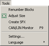
| − | | ''- reorder | + | | ''- reorder function blocks numbers on the diagram;'' |
|- style="padding:0px;line-height: 0.6;" | |- style="padding:0px;line-height: 0.6;" | ||
| ''- change the boundaries of the workspace by the contents of the diagram;' | | ''- change the boundaries of the workspace by the contents of the diagram;' | ||
|- style="padding:0px;line-height: 0.8;" | |- style="padding:0px;line-height: 0.8;" | ||
| − | | ''- | + | | ''- create a standalone firmware flash file;'' |
|- style="padding:0px;line-height: 0.6;" | |- style="padding:0px;line-height: 0.6;" | ||
| − | | ''- start CAN | + | | ''- start CAN monitor;'' |
|- style="padding:0px;line-height: 0.6;" | |- style="padding:0px;line-height: 0.6;" | ||
| ''- change CannyLab settings;'' | | ''- change CannyLab settings;'' | ||
| Line 194: | Line 194: | ||
| | | | ||
|- style="padding:0px;line-height: 0.8;" | |- style="padding:0px;line-height: 0.8;" | ||
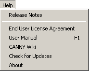
| − | | ''- | + | | ''- view CannyLab version history;'' |
|- style="padding:0px;line-height: 0.6;" | |- style="padding:0px;line-height: 0.6;" | ||
| ''- read END-USER LICENSE AGREEMENT file;'' | | ''- read END-USER LICENSE AGREEMENT file;'' | ||
| Line 204: | Line 204: | ||
| ''- check for CannyLab updates;'' | | ''- check for CannyLab updates;'' | ||
|- style="padding:0px;line-height: 0.6;" | |- style="padding:0px;line-height: 0.6;" | ||
| − | | ''- get information about | + | | ''- get information about the current program version.'' |
|} | |} | ||
=== Toolbars === | === Toolbars === | ||
| − | Toolbars allow access to the most | + | Toolbars allow access to the most used commands in CannyLab. |
[[File:4_4_2_1.png]] | [[File:4_4_2_1.png]] | ||
| − | Desktop Control Panel allows scaling | + | Desktop Control Panel allows scaling the area of the workspace and changing its dimensions in pixels. To quickly zoom in/out, rotate the mouse wheel while holding down the «Ctrl» button on your keyboard. |
[[File:4_4_2_2.png]] [[File:4_4_2_2a.png]] | [[File:4_4_2_2.png]] [[File:4_4_2_2a.png]] | ||
| Line 219: | Line 219: | ||
=== Workspace === | === Workspace === | ||
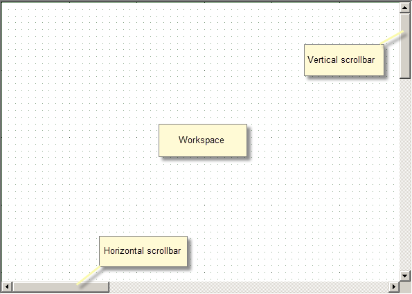
| − | + | The workspace is designed to display, edit, and debug function diagrams. The background of the workspace is a grid that facilitates positioning of function diagram elements. To move around the diagram displayed in the workspace, use the vertical and horizontal scroll bars, mouse wheel or arrow keys. | |
[[File:4_4_3_1.png]] | [[File:4_4_3_1.png]] | ||
| Line 225: | Line 225: | ||
=== Status bar === | === Status bar === | ||
| − | The status bar displays: for which | + | The status bar displays: the controller for which the current function diagram is designed, the status of communication with the controller, the presence of system software and function diagram in the connected controller. In the simulator mode the status bar displays information about controller resources used by the user diagram. |
[[File:4_4_4_1.png]] | [[File:4_4_4_1.png]] | ||
| − | === | + | === Function block panel === |
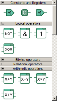
| − | + | Function block panel contains all block types available for constructing the function diagram. Function blocks in this panel are grouped by their purpose and, depending on display setting, may be presented as either icons or a list. Scroll the function block panel by using the vertical scroll bar or your mouse wheel. | |
| − | + | The two ways of displaying the function block panel: | |
{| | {| | ||
|[[File:4_4_5_1.png]] | |[[File:4_4_5_1.png]] | ||
| Line 240: | Line 240: | ||
|} | |} | ||
| − | === | + | === Function block by ordinal number search dialog=== |
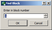
| − | Access | + | Access the dialog for searching function blocks by their ordinal number by selecting "Edit" → "Find block" in the CannyLab main menu. |
[[File:4_4_6_1.png]] | [[File:4_4_6_1.png]] | ||
| − | === | + | === Text search dialog === |
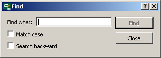
| − | Access | + | Access the dialog that allows searching by the specified text fragment by choosing "Edit" → "Find..." in the main menu of the program or by using the ''"Ctrl + F"'' key combination. |
[[File:4_4_6_2.png]] | [[File:4_4_6_2.png]] | ||
| + | |||
| + | If you’ve already used text search in the current session, you can continue searching for the currently entered text fragment by choosing "Edit" → "Find next"/pressing “F3” to find the next occurrence or by choosing "Edit" → "Find previous"/pressing “Shift+F3” to find the previous occurrence. | ||
=== Settings dialog === | === Settings dialog === | ||
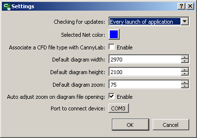
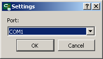
| − | Access | + | Access the CannyLab configuration dialog by selecting "Tools" → "Settings" in main menu. |
[[File:4_4_7_1.png]] | [[File:4_4_7_1.png]] | ||
| Line 261: | Line 263: | ||
|- valign="top" | |- valign="top" | ||
|width="300px"|Checking for updates - | |width="300px"|Checking for updates - | ||
| − | | | + | |Set how frequently the program checks for new software versions<br>[[File:4_4_7_2.png]] |
|- valign="top" | |- valign="top" | ||
|Selected Net colour - | |Selected Net colour - | ||
| − | |Choose selected connection line | + | |Choose the colour of a selected connection line |
|- valign="top" | |- valign="top" | ||
|Associate CFD file type with CannyLab - | |Associate CFD file type with CannyLab - | ||
| − | |Associates | + | |Associates function diagram file type with the current version of CannyLab |
|- valign="top" | |- valign="top" | ||
|Default diagram width - | |Default diagram width - | ||
| Line 279: | Line 281: | ||
|- valign="top" | |- valign="top" | ||
|Automatic selection of scale when opening a file - | |Automatic selection of scale when opening a file - | ||
| − | | | + | |Enables fitting the diagram to screen automatically when opening an existing file. |
|- valign="top" | |- valign="top" | ||
|Port to connect device - | |Port to connect device - | ||
| − | | | + | |Choose a COM port for connecting devices that use the RS-232 interface for downloading the software (CANNY 5, CANNY 5 nano, CANNY 5.2, CANNY 5 duo, CANNY 5.2 duo)<br>[[File:4_4_7_3.png]] |
|} | |} | ||
| Line 292: | Line 294: | ||
|- valign="top" | |- valign="top" | ||
|Ctrl+N | |Ctrl+N | ||
| − | |Create a new | + | |Create a new function diagram file; |
|- valign="top" | |- valign="top" | ||
|Ctrl+O | |Ctrl+O | ||
| − | |Open | + | |Open an existing diagram file; |
|- valign="top" | |- valign="top" | ||
|Ctrl+S | |Ctrl+S | ||
| − | |Save diagram file; | + | |Save the function diagram file; |
|- valign="top" | |- valign="top" | ||
|Ctrl+A | |Ctrl+A | ||
| Line 304: | Line 306: | ||
|- valign="top" | |- valign="top" | ||
|Ctrl+Z | |Ctrl+Z | ||
| − | |Undo the last action | + | |Undo the last action while working on the diagram; |
|- valign="top" | |- valign="top" | ||
|Ctrl+Y | |Ctrl+Y | ||
| − | | | + | |Redo the last undone action while working on the diagram; |
|- valign="top" | |- valign="top" | ||
|Del | |Del | ||
| Line 319: | Line 321: | ||
|- valign="top" | |- valign="top" | ||
|PageUp, PageDown | |PageUp, PageDown | ||
| − | |Shift workspace display area page up, down; | + | |Shift workspace display area one page up, down; |
|- valign="top" | |- valign="top" | ||
|Ctrl + mouse wheel | |Ctrl + mouse wheel | ||
| − | |Fast workspace | + | |Fast workspace zoom; |
|- valign="top" | |- valign="top" | ||
|Alt + mouse wheel | |Alt + mouse wheel | ||
| − | |Horizontal | + | |Horizontal scrolling within the workspace; |
|- valign="top" | |- valign="top" | ||
|Shift + mouse wheel | |Shift + mouse wheel | ||
| − | | | + | |Fast vertical scrolling within the workspace; |
|- valign="top" | |- valign="top" | ||
| − | | | + | |Hold mouse wheel + move the mouse |
| − | | | + | |Move the diagram field within the workspace ("drag and drop"). |
|- valign="top" | |- valign="top" | ||
|Double-click the left mouse button | |Double-click the left mouse button | ||
| − | |In | + | |In editor mode: on a network – open the rename network dialog; on a register – open the register editor dialog; on a constant – open the constant editor dialog with the last used option selected by default. In simulator mode: on a network – set/remove control point; on a function block – set/remove the breakpoint. |
|- valign="top" | |- valign="top" | ||
|Ctrl + double-click the left mouse button | |Ctrl + double-click the left mouse button | ||
| − | |In the simulator mode: | + | |In editor mode: on a constant – open the alternative constant editor dialog. In simulator mode: on a network – forcibly set the network value to "1"/remove the previously set value. |
|} | |} | ||
Revision as of 12:05, 10 December 2020
CannyLab user interface consists of a single window - the main program window.
Contents
Main window
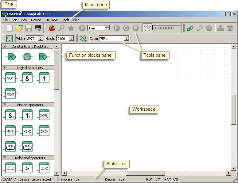
The main window is divided into several areas:
- window title;
- main menu;
- toolbar;
- function block panel;
- workspace;
- status bar.
Depending on the current operating mode of the editor, some of CannyLab menu items and panels may not be available or hidden.
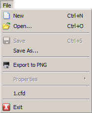
Menu "File" contains commands for working with CannyLab files.
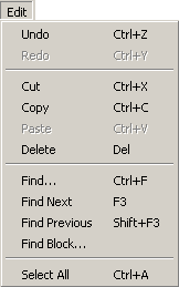
Menu "Edit" contains the basic editing commands for working with the function diagram editor.
Menu "View" contains options for customizing the appearance of the toolbar, the function block panel, as well as an option for scaling the workspace.

|
|
| - scale the workspace by the contents of the diagram; | |
| - toolbar appearance settings; | |
| - function block panel appearance settings. |
|
|
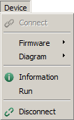
Menu "Device" contains commands for working with the controller.
| - upload firmware to the controller; | |
| - erase controller firmware; | |
| - upload the user's function diagram to the controller; | |
| - erase the user's function diagram from the controller. |
Menu "Simulation" contains controls for the controller software emulation mode in the CannyLab environment.

|
- use the decimal number system; |
| - use the hexadecimal system; | |
| - use the binary system; | |
| - use character data mapping. |
Menu "Service" contains service commands and CannyLab settings.
Menu "Help" provides links to this guide and information about the program.
Toolbars
Toolbars allow access to the most used commands in CannyLab.
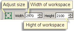
Desktop Control Panel allows scaling the area of the workspace and changing its dimensions in pixels. To quickly zoom in/out, rotate the mouse wheel while holding down the «Ctrl» button on your keyboard.
Workspace
The workspace is designed to display, edit, and debug function diagrams. The background of the workspace is a grid that facilitates positioning of function diagram elements. To move around the diagram displayed in the workspace, use the vertical and horizontal scroll bars, mouse wheel or arrow keys.
Status bar
The status bar displays: the controller for which the current function diagram is designed, the status of communication with the controller, the presence of system software and function diagram in the connected controller. In the simulator mode the status bar displays information about controller resources used by the user diagram.
Function block panel
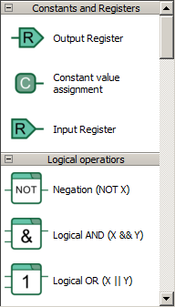
Function block panel contains all block types available for constructing the function diagram. Function blocks in this panel are grouped by their purpose and, depending on display setting, may be presented as either icons or a list. Scroll the function block panel by using the vertical scroll bar or your mouse wheel.
The two ways of displaying the function block panel:
|
|
Function block by ordinal number search dialog
Access the dialog for searching function blocks by their ordinal number by selecting "Edit" → "Find block" in the CannyLab main menu.
Text search dialog
Access the dialog that allows searching by the specified text fragment by choosing "Edit" → "Find..." in the main menu of the program or by using the "Ctrl + F" key combination.
If you’ve already used text search in the current session, you can continue searching for the currently entered text fragment by choosing "Edit" → "Find next"/pressing “F3” to find the next occurrence or by choosing "Edit" → "Find previous"/pressing “Shift+F3” to find the previous occurrence.
Settings dialog
Access the CannyLab configuration dialog by selecting "Tools" → "Settings" in main menu.
Keyboard shortcuts
| F1 | Open Reference Manual; |
| Ctrl+N | Create a new function diagram file; |
| Ctrl+O | Open an existing diagram file; |
| Ctrl+S | Save the function diagram file; |
| Ctrl+A | Select all; |
| Ctrl+Z | Undo the last action while working on the diagram; |
| Ctrl+Y | Redo the last undone action while working on the diagram; |
| Del | Delete selected diagram elements; |
| Esc | Exit network editing mode; |
| Left, Up, Right, Down | Shift workspace display area Left, Up, Right, Down; |
| PageUp, PageDown | Shift workspace display area one page up, down; |
| Ctrl + mouse wheel | Fast workspace zoom; |
| Alt + mouse wheel | Horizontal scrolling within the workspace; |
| Shift + mouse wheel | Fast vertical scrolling within the workspace; |
| Hold mouse wheel + move the mouse | Move the diagram field within the workspace ("drag and drop"). |
| Double-click the left mouse button | In editor mode: on a network – open the rename network dialog; on a register – open the register editor dialog; on a constant – open the constant editor dialog with the last used option selected by default. In simulator mode: on a network – set/remove control point; on a function block – set/remove the breakpoint. |
| Ctrl + double-click the left mouse button | In editor mode: on a constant – open the alternative constant editor dialog. In simulator mode: on a network – forcibly set the network value to "1"/remove the previously set value. |
