|
|
| Line 240: |
Line 240: |
| | | | |
| | <!--NOPDF--> | | <!--NOPDF--> |
| − | == Смотри также == | + | == See also == |
| | [[CANNY 5.2 duo]] | | [[CANNY 5.2 duo]] |
| | | | |
Revision as of 14:55, 22 December 2016
Общее описание
Драйвер UART, через USB Virtual COM-port, позволяет контроллеру CANNY 5.2 duo обмениваться данными с внешними устройствами, например ПК, в процессе выполнения пользовательской диаграммы.
Объем приемного и передающего буферов данных драйвера UART CANNY 5.2 duo составляет 24 байта.
Набор поддерживаемых скоростей ограничен: 300, 1200, 2400, 9600, 19200, 57600, 115200 бод; а также доступен только один формат передачи данных: 8-N-1.
| Note:
|
For correct operation of all protocols based on the UART / RS-232 requires that all GND terminals of the devices committing communication, were given to a single potential ("common ground").
|
| Примечание:
|
Для возможности обмена данными между контроллером и внешним устройством, например ПК, через USB Virtual COM-port необходимо, при задании настроек драйвера использовать только конфигурацию RS-232 (инверсная полярность).
|
Driver registers
The following describes the acceptable and returnable values of the driver control operation registers.
UART Driver Configuration Registers.
| Register
|
Expected values
|
| UART1 Mode Setup Register
|
| 1...N
|
=
|
set driver configuration, which determines current operation mode and parameters (given the special constant from the constants directory);
|
| 0
|
=
|
driver UART1 is desable;
|
|
| UART1 Receive Timeout Setup Register, bits
|
| 1...65535
|
=
|
stop data reception, if during the time for which a specified number of data bits can be recd, line was not recorded any potential change and the line is in the passive state;
|
| 0
|
=
|
use the default value defined in channel (13) configuration.
|
|
UART driver configuration is determined by the constants that represent the combination of parameters that determine the speed, mode, additional date transmission parameters and line potential in the passive mode.
| Parameter
|
Acceptable values
|
| The data rate, bps
|
300, 1200, 2400, 9600, 19200, 57600, 115200
|
| Mode
|
UART 8-N-1
|
| Полярность
|
прямая (UART); инверсная (RS-232)
|
Named constants that represent UART configuration parameters combination, available to the user in the "UART configuration" CannyLab constants directory, which can be accessed via function block entry context menu having "constant" type.
| Примечание:
|
Для возможности обмена данными между контроллером и внешним устройством, например ПК, через USB Virtual COM-port необходимо, при задании настроек драйвера использовать только конфигурацию RS-232 (инверсная полярность).
|
UART Diagnostic Registers.
| Register
|
Return values
|
| UART1 Overflow Register
|
| 1
|
=
|
UART buffer is full;
|
| 0
|
=
|
No overflow detected.
|
|
| UART1 Idle Register
|
| 1
|
=
|
no activity on the corresponding channel UART drivers, the line is in a passive mode;
|
| 0
|
=
|
fixed activity on the line of corresponding channel UART driver.
|
|
| UART1 Receive Error Register
|
| 1
|
=
|
during UART data reception an error occurred;
|
| 0
|
=
|
the driver is operating normally.
|
|
| UART1 Ready To Send Register
|
| 1
|
=
|
UART driver data transmit buffer is free;
|
| 0
|
=
|
UART driver data transmit buffer is busy, data transmission not possible.
|
|
UART Receive Registers.
| Register
|
Expected values
|
| UART1 Data Set Ready Register
|
| 1
|
=
|
the message is received and placed into corresponding UART channel receive buffer;
|
| 0
|
=
|
in the corresponding UART driver channel receive buffer no actual data present.
|
|
| UART1 Received Data Length Register
|
| 0...24
|
=
|
a value, equal to the number of data bytes in the packet received via respective UART channel..
|
|
| UART1 Received Data Register D1:D0
|
| ...
|
| UART1 Received Data Register D23:D22
|
|
| 0...0xFFFF
|
=
|
respective data byte values, UART reception buffers of each channel by two bytes to the register.
|
|
UART Transmit Registers.
| Register
|
Expected values
|
| UART1 Request To Send Register
|
| ≥ 1
|
=
|
to load data from the transfer registers in the respective channel UART transmit buffer;
|
| 0
|
=
|
do not load data to the respective channel UART transmit buffer.
|
|
| UART1 Transmit Data Length Register
|
| 0...24
|
=
|
the number of data bytes that will be transmitted to the line, when receiving a command to send on the corresponding channel of UART driver.
|
|
| UART1 Transmit Data Register D1:D0
|
| ...
|
| UART1 Transmit Data Register D23:D22
|
|
| 0...0xFFFF
|
=
|
values of the respective data bytes for transmission via respective UART driver channel, two bytes to the register.
|
|
Controller operation in UART mode
Operating in UART mode, the controller can perform duplex data transmission/reception.
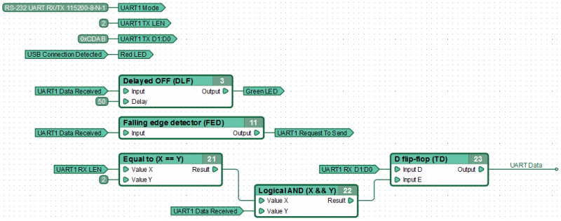
Пример функциональной диаграммы для обмена данными по UART через Virtual COM-port. Контроллер, получив сообщение длиной 2 байта по интерфейсу UART1, сохраняет их в соответствующей именованной сети для дальнейшей обработки и на следующем цикле выполнения диаграммы отправляет обратно заранее подготовленные 2 байта данных. Подключение к ПК, через разъем USB, подтверждается включением красного светодиода контроллера. Получение данных по UART контроллер подтверждает кратковременным включением зеленого контрольного светодиода.
See also
CANNY 5.2 duo
CANNY 7, UART Driver
