| This documentation is out of date.
The new version of the documentation is here: https://cannylogic.com/docs |
CANNY 5.3 pico
CANNY 5.3 pico is small-sized, cost-effective automotive programmable logic controller with CAN 2.0A/B interface, three general purpose IO channels, up to two LIN interfaces and protected ADC.
Contents
General Information
Due to limited external channels, programmable logic controller CANNY 5.3 pico may be attributed to a class of smart relays or Nano PLC. CANNY 5.3 pico is capable of solving many automation, controlling and monitoring tasks.
CANNY 5.3 pico has the following unique features and combinations:
- three universal input / output channels that can work in the modes of outputs and inputs, with both positive and negative polarity;
- rated power supply and IO channels voltage 0 / 12V (16V max);
- the maximum output current of each of the three IO channels +/- 100mA, sufficient to control usual automotive relay;
- one CAN 2.0B Interface, compliant with ISO-11898, SAE J2411 widely used in modern cars;
- support for popular communication protocols: 2 UART, 2 LIN, 1-Wire Dallas* (* - in developing);
- built-in energy consumption management in the range of 1 to 25mA, helps to conserve battery power during period of inactivity in a car;
- EEPROM for applications and sixty-four 16-bit non-volatile memory data cells, available to user application to preserve critical data during a power failure;
- wide operating temperature ranged from -40 to +85°C;
- Integrated surge protection and short circuit protection;
- compact dimensions that allow it to be mounted in places of limited capacity and even in vehicle wiring harnesses, as well as use the controller as a built-in.
To develop custom software for CANNY 5.3 pico, use graphical programming language CFD to quickly create user-effective applications - Functional Diagrams. The free of charge IDE CannyLab contains tools for editing, debugging and writing software to the controller.
Requirements for writing software to the controller:
- PC with a USB port version 1.1 or higher
- Installed CannyLab IDE
- Ordinary miniUSB cable
Controllers' memory accessible to user is enough to accommodate the program, consisting of several hundred functional blocks, which allows for fairly sophisticated algorithms.
A On-board LED, controlled from the user application, are useful to indicate controller or debugging mode.
Design and functional operation
The appearance and layout
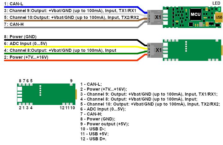
The main components of CANNY 5.3 pico are: a micro controller (MCU) with the auxiliary circuits, power supply system for all controllers' elements, IO channels level matching circuit, electric protection system, connector and LED, based on a single printed circuit board 40 x 15 mm. The controller has microUSB connector and pads for soldering wires or installing an 8-pin double-row connector. Depending on the configuration for connecting the controller to a power source and external devices, a set of wires or a harness with an 8-pin double-row connector, as well as a heat-shrink tubing, may be included in its package. On 8 pin/8-pin double-row connectors are located: power input +7V...+16V, power input GND, CAN-H, CAN-L, three contacts corresponding to input-output channels 8, 9 and 10 controller, ADC contact. The microUSB connector of the controller is used to connect the interface cable connecting the controller to the PC.
All contacts of the 8-pin connector are additionally located on special edge contacts located on the long sides of the controller board and can be used to solder CANNY 5.3 pico to the user's motherboard. In addition, the contacts of the microUSB connector are also located on the sides of the board, which allows the user to conveniently place the connector for connecting the controller to the PC to update the controller software when installing the controller on the motherboard.
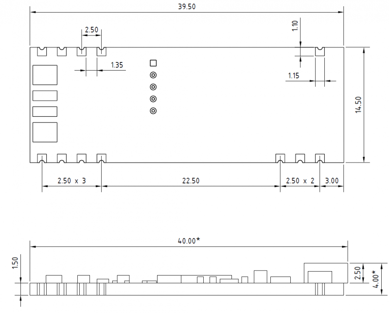
Overall and installation dimensions of the controller
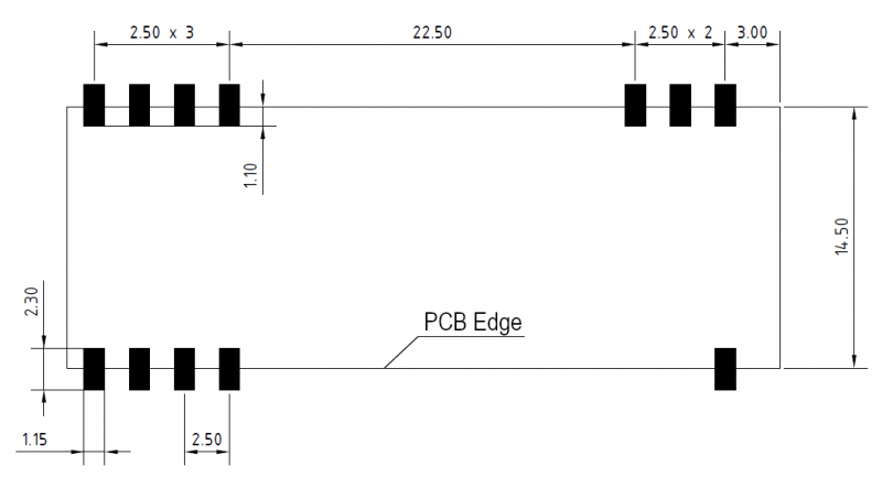
Recommended dimensions and location of pads for surface mounting of the controller
Software Architecture
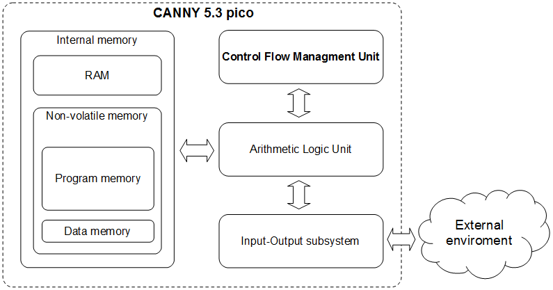
CANNY 5.3 pico is a digital programmable computing control device. CANNY 5.3 pico main structural elements are: arithmetic logic unit (ALU), internal memory, commands execution management subsystem and input-output system.
Arithmetic Logic Unit is the processing core of CANNY 5.3 pico. ALU provides system software and user functional execution diagram placed into the internal memory of the controller. Controller's internal memory is divided into the EEP program memory, EEP data memory, and ROM. The command's management subsystem is responsible for switching and setting mode of the controller. The IO system provides controllers' communication to the outside world, using both discrete IO channels and standard digital interfaces CAN / LIN / RS232 / USB.
Software Structure
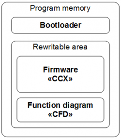
Software CANNY 5.3 pico consists of: a bootloader, system software (operating system and drivers), and a custom function diagram.
The bootloader provides the controller with the software download mode, organising data transmission between CANNY 5.3 pico and PC using USB protocol. It checks the data integrity transmitted from the PC and loading to the controllers' internal memory. The bootloader placed into the internal memory of the controller during production and can not be deleted or modified by the user. The manufacturer distributes CANNY 5.3 pico firmware in CCX file format. It includes an operating system and a set of drivers providing function diagram execution and its interaction with the controllers' resources. The contents of various CCX files can be reloaded into the controller by user but user is restricted to modify CCX file content.
Custom block diagram is created and modified in CannyLab IDE, then it can be loaded into the controller where it specifies the algorithm to work standalone or saved in to CFD file.
Operation modes
There are several operation modes to perform basic operations with controller.
Software upload mode
In this mode, the controller is running bootloader to load firmware, and functional diagram under CannyLab management. Controller switch to this mode automatically when connected to PC with USB cable. During the transition to SW upload mode the controller performs a master reset: the functional diagram execution stops, IO channels are switching to neutral state, built-in green LED turns on. When controller establishes communicating with the PC software, the green LED goes into flickering mode. Exit from this mode happens automatically when the connection to the PC is disrupted. At the end of the software download mode, if EEPROM system software is loaded correctly, the controller will switch to running mode, otherwise it returns to SW download mode.
Running mode
Running mode is the main controllers' mode. In this mode, the controller is running continuously under system software sequence, in an endless cycle, performing the functional diagram, working on the algorithm specified by the user. Transition to this mode takes place automatically when the controller is connected to an external power supply +7V...+16V and the absence of the USB connection. When operating in this mode, the functional diagram has access to all resources of the controller and drivers included in the controllers' system software.
Sleep mode
This mode is an option of normal running mode in which, after each cycle of execution of a function diagram, the controller pauses to reduce its power consumption to a minimum. Thus, the controller operates in a pulsed mode, periodically "asleep" and "waking up". Enable, disable, and configure the parameters of this mode are controlled by the functional diagram. Using this mode is relevant when developing systems, focused on battery-power, such as the on-board car equipment.
Runtime Environment
Functional diagram presentation
The graphical block diagram developed in CannyLab environment, automatically processed by the translator just before loading to the controller. CannyLab checks on the consistency of the diagram, determines function blocks execution order and converts the diagram into the executable code - a sequence of machine instructions CANNY 5.3 pico controllers' ALU.
The execution order
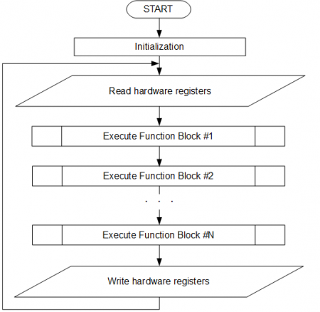
Executable program code during loading into the controller already contained system software, is including in the sequence of the system software machine instructions. Thus, the aggregate command sequence loaded with system software and functional diagram, will be: initialisation routines executed once after each controllers' reset and executable functional diagram code, framed with the controller resources' procedure management, and placed in an infinite executable loop - diagrams running loop. Some of the drivers included in the controller system software, such as CAN driver, require controller to raise immediate response during data transmission and reception of program events. Program code of these drivers asynchronously processed by the controller in parallel with the main execution flow. In the processing of asynchronous drivers calls, the diagrams main run loop performance is briefly suspended.
Access to hardware resources
All available resources to the user from the functional diagram : the system resources of the controller, IO subsystem and additional drivers included in the system software, appears on a controllers' internal memory protected address space. This address space is divided into read-only registers and write-only registers.
The user is able to specify the read-only register address as a source of input data from virtually any function block of a diagram. Thereby extract and use to implement their own algorithms, data received by the controller from the outside world. For example information about the electric potential on any controllers' terminal, or the data packet contents received from the CAN bus. Write-only register address can be used as the output target for any functional block on the diagram. Thus, the user controls the resources of the controller from functional diagrams which gives an opportunity to influence the objects of the outside world. For example: switch external relay by changing the electrical potential on one of the pins of the controller, turn LED on; set CAN operation mode; send a data packet.
The most resources used include assignment required operating parameters, such as the polarity of the output channels, the polarity and the sensitivity of the input channels, CAN communication speed and so on.
Specifying these parameters is made in the form of recording specific constants in one or a few specific registers, depending on a required set of resources configuration. For example, copying a constant with a value of 260 in the register located at 1349 address is set channel #8 to an output positive polarity mode.
In CannyLab IDE, for user convenience, all the of the controllers' available registers are named, as well as all special constants that are used in interaction with the controllers' resources. Therefore, for CannyLab user this operation will look as setting the constants named "Strong VDD/Weak GND" at the input of the function block "Copy" and setting the address with the name "DIO Output Mode Setup Register, IO Channel 8" at its output.
Having thus established channel #8 mode, by the appearance of the value "1" in the register located at 1064 address ("DIO Input Value Register, IO Channel 8"), we can learn about the application of a positive electric level to contact #4 of X1 connector.
Controllers' Registers
System Registers
- Main article: CANNY 5.3 pico, System Registers
System resources are divided into an address group of read registers and an address group of write registers. Referring to the given registers from the functional diagram, you can get demanding information for practical application about the current status of the controller, and control its operational mode. The set of system registers located in the "System Registers" directory of CannyLab IDE registers list are accessible via "Input Register" and "Output Register" context menu.
Discrete Inputs and Outputs
- Main article: CANNY 5.3 pico, Discrete IO Driver
Users CANNY 5.3 pico has three discrete input-output general purpose channels available. Each channel is physically presented to the appropriate pins of controller: channel 8 - contact 4; channel 9 - contact 3; channel 10 - contact 5. Writing and reading data of the respective drivers registers, the functional diagram can manage the electric potential in each of these contacts and get information about current value of potential on each of them.
Channels physical characteristics allows to connect to them a variety of external actuators - electromagnetic relays, small motors, LEDs. As an external digital input signals it is possible to use a mechanical, electromechanical, and electronic buttons and switches, pulse generators, voltage source 0-12V and transistor outputs of various equipment, etc.
Channels operation mode and parameters specified by function diagram. At any given time, the channel can only work in one of the possible modes, but it is possible to dynamic override the channel configuration from the functional diagram during execution.
High Resolution PWM
- Main article: CANNY 5.3 pico, HR PWM Driver
One input-output channel of CANNY 5.3 pico (channel 8) supports operation in the mode of a high-frequency pulse-width modulator, herewith the period and duty cycle are set in the range from 2 to 32767 microseconds, in increments of 1 microsecond.
In HR PWM, the channel has a fixed pulse polarity - GND 100mA. Generation can be conducted in either open collector (no pull-up lines or external pull-up) or with internal pull-up to supply voltage (specified by setting the value in the appropriate register). In this mode, the channel is asynchronous to functional diagram, which allows maximum timing stability of generated signal.
The driver of high resolution pulse width modulator (HR PWM) operates using Discrete Inputs and Outputs resources, wherein, having a higher priority. Thus, upon activation of the HR PWM driver, controller channels used are unavailable to input-output drivers.
| Note: | In high resolution pulse width modulator mode, the electrical protection from short circuit is disabled! Overload or channel short-circuit in high resolution PWM mode can lead to controller failure! |
CAN driver
- Main article: CANNY 5.3 pico, CAN Driver
Two dedicated external outputs of CANNY 5.3 pico controller, contact 1 (CAN-L) and contact 7 (CAN-H), provided for connection to digital information CAN-bus.
UART / RS232 / Modbus driver
- Main article: CANNY 5.3 pico, UART Driver
Two IO channels (#9 and #10) CANNY 5.3 pico supports UART, RS-232 serial protocols data transmission/reception. It may be used to connect the controllers with each other or with external equipment supporting this communications protocols. The channels may be activated independently of each other and have individual data speed setting, protocol type and configuration, pull up line.
Size of receive and transmit buffers for each of the interfaces of the UART CANNY 5.3 pico driver is 64 bytes.
UART implementation in CANNY 5.3 pico controllers allows to organize serial data reception and transmission over a single wire in half-duplex mode. Thus CANNY7 may have two independent connections using the UART protocol. Monitoring of the data link status should be done from the functional diagram. If the channel is free, the device may start data transmitting , otherwise the device should wait for the line release.
RS-232 implementation by using both UART data channels , allows to exchange data with other RS-232 device in a duplex mode, i.e. one channel to perform data sending and on the other to simultaneously receive data.
Modbus protocol in CANNY7 controllers implemented as over UART as over RS-232. As ADU (Application Data Unit) used compact binary option Modbus RTU. Checking the data integrity carried out by automatically calculated checksum (CRC). Package size is limited to 64 bytes including the CRC.
LIN driver
- Main article: CANNY 5.3 pico, LIN Driver
Two input-output channels of CANNY 5.3 pico, which can be placed under control of UART/RS-232 driver (Channel 9 and 10), can be used to organize data reception and transmission as two independent LIN driver channels.
LIN driver channels can be connect both together and individually, have individual baud rate settings , pull-up line and bus node type- MASTER or SLAVE.
LIN driver in its operation uses the resources of controller channels, but has a higher priority than discrete input-output driver. Thus, upon LIN driver activation, for the involved channels in its operation, changing values in registers associated controllers' discrete input-output driver will be ignored.
User Preprogrammed Parameters
- Main article: CANNY 5.3 pico, User Preprogrammed Parameters
The user preprogrammed parameters can be set by the end user during loading a software to the controller with Firmware Update Utility. After loading the software and launch the controller in stand-alone mode, the user-defined data become available to the functional diagramin in relevant controller registers.
Proper use of user parameters greatly increases the flexibility and versatility of the controller-based solutions, alloving the end user without expirience working with CannyLab, make safe changes in the operation of the controller algorithm using a simple user interface.
EEPROM Non-volatile Memory
- Main article: CANNY 5.3 pico, EEPROM Driver
To eliminate loss of critical information (state of the controller, external devices status, and so on..) in case of power reset, CANNY 5.3 pico controller equipped with non-volatile memory. The values saved in EEPROM will be available in special registers after the power is restored.
There are 64 16-bit non-volatile memory cells, which are accessed by corresponding read and write registers.
| Note: | Working with non-volatile memory does not require any special pre-configuration. |
Analog-to-digital converter (ADC)
- Main article: CANNY 5.3 pico, ADC Driver
CANNY 5.3 pico supports Analog-to-Digital Converter (ADC) mode for one special pin (contact #6) of the connector X1. This ADC converter can be used to measurement the input voltage from 0 to 5V with 12-bit resolution and 1 millisecond sample rate
ADC driver is always active.
Specifications
Electrical characteristics and environmental requirements
| Supply voltage | 7...16 V | |
| Current consumption: | in operation (no more than) | 22 mA |
| in power saving mode (not more) | 1 mA | |
| The maximum current of each channel in output mode | +100 mA / -100 mA | |
| Operating temperature range | -40oС...+85oС | |
| Ingress Protection Rating | IP50 | |
Electrical circuits protection:
- from channel short-circuit - software;
- from channel overload - internal current-limiting fusing resistors;
- from power supply reverse polarity - internal diode;
- high emissions suppression circuit during inductive loads switching on channels 8, 9, 10 - diode and varistor.
Safety Precautions
The circuits of the controller do not have life-threatening voltage. Controller open terminals are under voltage during operation. Any connections to the controller and maintenance are made only with the power off to the controller and connected devices..
Installation and connection
Installation and connection of the controller must be carried out only by qualified personal studied this documentation. Controller installation must be carried out in suitable areas to operation conditions of the controller.
Do not allow moisture comes in contact with output terminals and internal elements of the controller. It is forbidden to use the controller in the presence of ambient acids, alkalis, and other corrosive substances.
Installing the controller and the cables laying connected to it must be done at a distance of not less than 0.3 meters from the high-voltage power lines and strong electromagnetic sources - power relays, contactors, gas discharge lamps. Avoid getting moisture on the controller enclosure at the installation site.
Transportation and storage
Controllers transported by all types of covered transportation. Placing and securing the shipping container with the packed devices in vehicles must provide their stable position and to prevent movement during transport.
Transportation and storage should be carried out at ambient temperatures from minus -40 to +85 ° C and relative humidity - up to 80%, compliance with security measures of protection from shock and vibration. The air must not contain acids, alkalis and other aggressive substances. Controllers should be stored on shelves.
