General description
Two input-output channels of CANNY 5.3 pico, which can be placed under control of UART/RS-232 driver (Channel 9 and 10), can be used to organize data reception and transmission as two independent LIN driver channels.
LIN driver channels can be connect both together and individually, have individual baud rate settings , pull-up line and bus node type- MASTER or SLAVE.
LIN driver in its operation uses the resources of controller channels, but has a higher priority than discrete input-output driver. Thus, upon LIN driver activation, for the involved channels in its operation, changing values in registers associated controllers' discrete input-output driver will be ignored.
Driver registers
The following describes the acceptable LIN driver operation control registers values.
LIN driver configuration Registers allows to set up the controller as a LIN bus node:
| Address
|
Expected values
|
|
|
| 1...N
|
=
|
setup a LINx driver channel configuration, determines the current operation mode and parameters (determined by special constant from the constants directory);
|
| 0
|
=
|
disconnect the channel from the LINx driver, return channel control to input-output channels driver and allow its status changes from the functional diagram.
|
|
Channel configuration for operation in this mode is determined by a constant, which is a combination of parameters: protocol version , baud rate, operation mode and the availability of internal channel pull-up.
| Parameter
|
The list of acceptable values
|
| LIN protocol version
|
1.3; 2.0
|
| baud rate
|
2400; 9600; 10500; 19200
|
| Operation mode
|
MASTER; SLAVE
|
| Pull-up
|
plus; float
|
Named constants that represent LIN configuration parameters combination, available to the user in the "LIN Modes" CannyLab constants directory, which can be accessed via function block entry context menu having "constant" type.
LIN driver diagnostic registers.
| Address
|
Return Values
|
|
|
| 1
|
=
|
corresponding channel LINx buffer is full;
|
| 0
|
=
|
corresponding channel LINx no buffer overflow detected.
|
|
|
|
| 1
|
=
|
during LINx data reception an error occurred;
|
| 0
|
=
|
the driver is operating normally.
|
|
| LINx Ready to Send Register
|
|
| 1
|
=
|
corresponding channel LINx data transmit buffer is free and ready;
|
| 0
|
=
|
LINx driver data transmission buffer is busy.
|
|
| LINx SLAVE Data Delivered Register
|
|
| 1
|
=
|
in SLAVE mode, successful data transfer indication from the buffer of corresponding channel LINx, in response to MASTER node request;
|
| 0
|
=
|
when the corresponding LINx channel is in a SLAVE mode, there were no MASTER node request received.
|
|
| LINx SLAVE Extendet Transmitting Buffers Data Delivered Flags Register
|
|
| 1...15
|
=
|
when working in MULTISLAVE mode: a sign of successful sending of data from the extended transmission buffer of the corresponding LINx driver channel in response to a request from the MASTER node; upon successful sending, the value "1" is assigned to a bit whose number will coincide with the number of the sent extended SLAVE buffer, i.e. upon successful sending, buffer No. 0 - flag register = 1 = 0x01 = 0b0001, buffer No. 1 - flag register = 2 = 0x02 = 0b0010, buffer No. 2 - flag register = 4 = 0x04 = 0b0100, buffer No. 3 - flag register = 8 = 0x08 = 0b1000;
|
| 0
|
=
|
there no was request from the MASTER node to receive data from nodes, numbers to which access to extended LINx SLAVE buffers is assigned when the LINx driver was work in MULTISLAVE mode.
|
|
LIN Receive Registers.
| Address
|
Return Values
|
| LINx Data Set Ready Register
|
|
| 1
|
=
|
the message is received and placed into corresponding LINx channel receive buffer;
|
| 0
|
=
|
in the corresponding LINx channel receive buffer no actual data present.
|
|
| LINx Received Data Register LEN
|
|
| 0...8
|
=
|
a value, equal to the number of data bytes in the packet received via respective LINx channel.
|
|
| LINx Received Data Register ID
|
|
| 0...0x3F
|
=
|
message ID, obtained via respective channel LINx. (See note.)
|
|
| LINx Received Data Register D1:D0
|
| ...
|
| LINx Received Data Register D7:D6
|
|
| 0...0xFFFF
|
=
|
respective data byte values, LINx reception buffers of each channel by two bytes to the register.
|
|
| Note:
|
LIN Received Data Register ID displays only the lower 6 bits of the identifier: 4-bit address of the device and the 2- bits used in the LIN 1.1 to encode the message length, and later to expand the address. 10 higher bits of LIN received message ID register always zero.
|
LIN transmit registers.
| Address
|
Expected Values
|
| LINx Request to Send Register
|
|
| ≥1
|
=
|
to load data from the transfer registers in the respective channel LINx transmit buffer;
|
| 0
|
=
|
do not load data to the respective channel LINx transmit buffer.
|
|
| LINx SLAVE Extended Transmitting Buffer Number
|
|
| 0...3
|
=
|
in MULTISLAVE mode: the number of the extended SLAVE transmission buffer of the corresponding LINx driver channel, the filling of which is carried out on this diagram execution cycle.
|
|
| LINx Transmit Data Register LEN
|
|
| 0...8
|
=
|
style="padding-left:0.5em;"the number of data bytes that will be transmitted to the line when receiving a command to send on the corresponding LINx channel.
|
|
| LINx Transmit Data Register ID
|
|
| 0...0x3F
|
=
|
LIN ID value for message transmission via respective LINx channel.
|
|
| LINx Transmit Data Register D1:D0
|
| ...
|
| LINx Transmit Data Register D7:D6
|
|
| 0...0xFFFF
|
=
|
data byte values to transmit on respective LINx channel by two bytes to the register.
|
|
| Note:
|
When sending LIN-messages, the driver discards all but the lower 6 bits of LIN ID register, automatically generates two parity bits and complements them ID, according to requirements of the standard.
|
| Note:
|
When working with LIN networks versions below 1.3, be careful in the formation of outgoing messages. The driver allows the use of combinations of length and identifier transmitting message unacceptable in this standard.
|
| Note:
|
If in the SLAVE mode LINx SLAVE Extended Transmitting Buffer Number Register is not used, that is, the extended LIN SLAVE buffers are not full, the driver operates in the usual SLAVE mode with one LIN transfer buffer.
|
| Note:
|
If in the SLAVE mode extended LIN SLAVE buffers is full using the register of the LINx SLAVE Extended Transmitting Buffer Number, the driver operates in MULTISLAVE mode.
|
| Note:
|
In MULTISLAVE mode, the extended LIN SLAVE buffers are filled sequentially, one at a time in the diagram execution cycle.
|
CANNY 5.3 pico in MASTER mode
To switch LIN driver channel in to MASTER mode, it is necessary to copy the constant value corresponding to the selected mode in to appropriate driver channel address: "LINx Mode Setup Register».
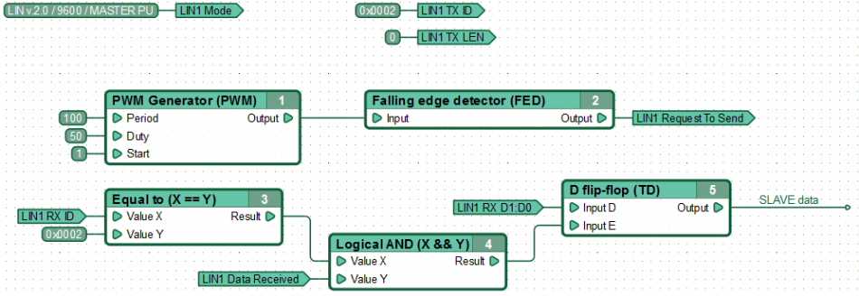
For MASTER to receive data from SLAVE-node, need to send corresponding request to LIN bus: Send the message header contains the identifier of the slave node from which the data is requested. The length of transmission message LEN LEN must be set to zero, in to transmission start register to be recorded non-zero value. Upon receipt of response from the slave, the data will be placed in receive register of the corresponding LINx driver channel with simultaneous setting mark in LINx Data Set Ready Register data availability.
An example of a functional diagram for MASTER data reception from SLAVE-node. MASTER every 100ms sends the data request from the slave with the identifier 0x02. After receiving a response, the controller stores the first 2 bytes of data in the D-flip-flop.
For data transmission in MASTER mode, the ID and Data registers must be filled, while setting transmission LIN LEN Register, a value equal to the number of transmitting data bytes, which must be greater than zero but less than nine. Instruction for LIN driver to send messages obtained by setting a non-zero value in the "LINx Request To Send Register". As a result, the contents of the registers is copied into the transmit buffer LIN, if it is free, the driver will immediately proceed to send a message.
| Note:
|
To prevent data loss, before sending a new LIN message, it is recommended to ensure readiness to the transfer of the next message from corresponding LIN channel transmit buffer, by checking the LINx Ready To Send Register.
|
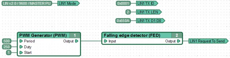
Example of functional diagram, sending data to the LIN bus by MASTER.
MASTER every 100ms sends a message to the bus with the identifier 0x01 that contains 2 bytes of data (0h0A and 0x55).
| Note:
|
If LINx Request To Send Register permanently set a non-zero value, then the attempt to copy the data to the transmission buffer for sending LIN messages will be taken at each diagram execution cycle. To avoid overflow of LIN transmission buffer, triggers the start of data transmission by single pulse using, for example, front detector functional blocks.
|
CANNY 5.3 pico in SLAVE mode
Operating SLAVE mode, LIN node successfully receives any data transmitted over the network, but can not transmit data to the LIN itself, without not having received the request from MASTER.
To switch LIN driver channel in to SLAVE mode, it is necessary to copy the constant value corresponding to the selected mode in to appropriate driver channel address: "LINx mode setup register».
To ensure successful data sending for node in SLAVE mode on MASTER-node request ,It must advance without waiting for a request, to prepare the data for transmission. This requires to fill in all the necessary LINx Transmit Data Register, namely: LIN ID register, message length register LIN LEN and place sending information in LIN data register.
Permission to send is given by setting a value "1" to "LINx Request To Send Register", whereby the contents of data registers is copied into LIN transmit buffer, if it is free. Sending of data, once placed in the buffer will be automatically performing by LIN driver, with each request from the MASTER.
| Note:
|
If LINx Request To Send Register permanently set a non-zero value, then the attempt to copy the data to the transmission buffer for sending LIN messages will be taken at each diagram execution cycle. To avoid overflow of LIN transmission buffer, triggers the start of data transmission by single pulse using, for example, front detector functional blocks.
|
Monitor a request reception from the MASTER and successful automatic response to it by LIN driver in SLAVE mode possible by the appearance of the value "1" in LINx Data Delivered Register. Update data in the buffer transmission is possible after its release. Status of the send buffer can be tracked by the value of the corresponding register.
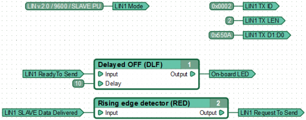
An example of a functional diagram for data transmission by LIN node in SLAVE mode.
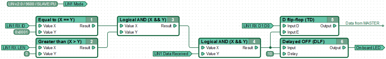
An example of a functional diagram SLAVE receiving data from the MASTER. Controller, receiving message with the identifier 0x01 that contains any data, stores the first two bytes of data message in the D-flip-flop.
CANNY 5.3 pico in MULTISLAVE mode
When operating in MULTISLAVE mode, each LIN controller interface can act as several (maximum four) LIN SLAVE nodes, i.e. answer MASTER requests by multiple IDs.
The driver of the corresponding LIN interface switches to MULTISLAVE mode automatically when LINx SLAVE Extended Transmitting buffers is filled data.
When from MASTER received a request to receive data from a LIN network node, the identifier of which is assigned to one of the additional LINx SLAVE buffers, the data will be transferred automatically, asynchronously with the operation of the functional diagram.
Information on the successful sending of data from extended LINx SLAVE buffers is available to the user through LINx SLAVE Extendet Transmitting Buffers Data Delivered Flags Register.
Extended LINx SLAVE buffers are filled with data through the registers common to all buffers: LINx Request to Send Register, LINx Transmit Data Register LEN, LINx Transmit Data Register ID and LINx Transmit Data Register Dy:Dz.
In this case, the data and message ID are placed in the buffer whose number (from 0 to 3) is set in the LINx SLAVE Extended Transmitting Buffer Number at the time of writing to the LINx Request to Send Register value 1.
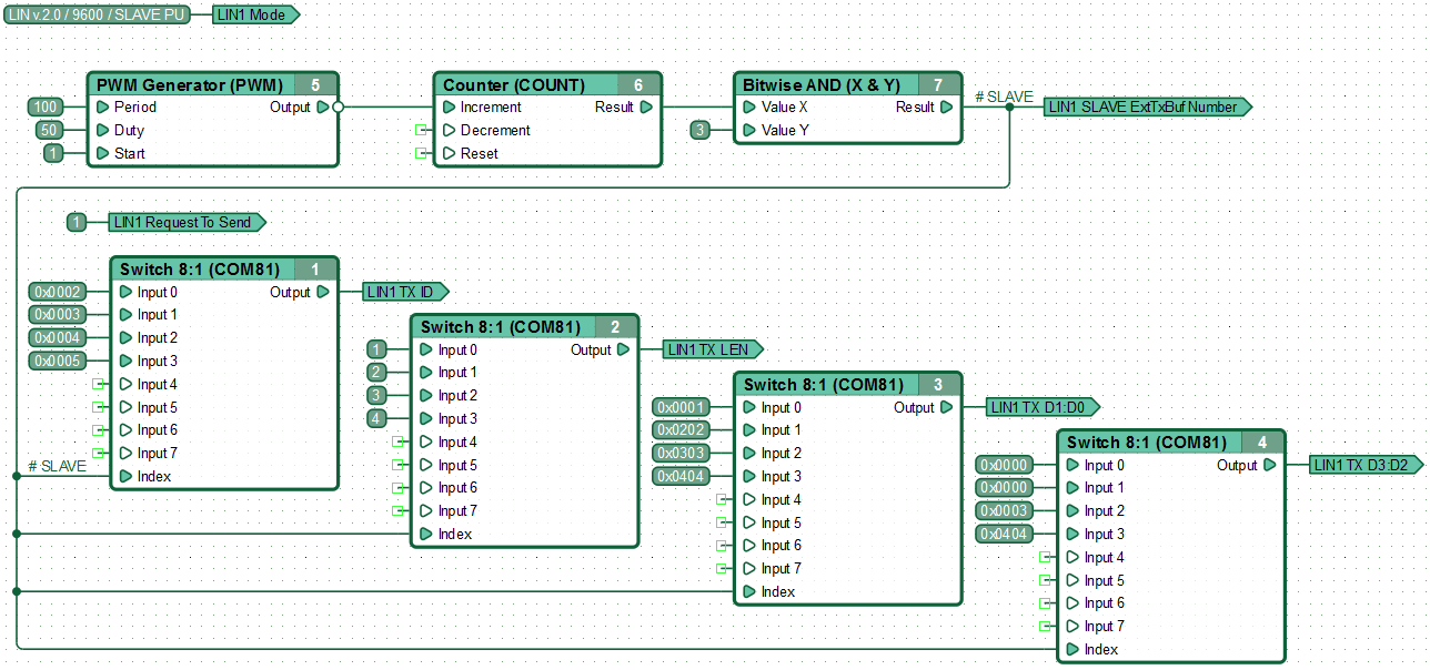
An example of the operation of the controller in MULTISLAVE mode, in which, after power is supplied, 4 additional LIN1 SLAVE transmission buffers are filled and constantly updated. Buffers are filled sequentially, one at each diagram execution cycle:
In fact, the operation of the LIN interface in SLAVE mode is the work in MULTISLAVE mode with one transmit buffer used - buffer #0.
Energy saving mode (low power consumption mode)
To save energy, LIN specification provides the ability to switch all LIN network nodes in low energy consumption mode. Most often, such a transition is initiated by master node by sending an appropriate message to the bus,or slave nodes switch by their own, when there is no activity on the bus for a specified time interval. Exit sleep mode can be initiated by any node on the bus. MASTER-node initiates LIN bus awakening by normal query slaves. However, waking up initiated by SLAVE-node is carried by short installation of GND potential on the line.
In the LIN driver of controller CANNY 5.3 pico, to wake the BUS, MASTER-node just need to start transmitting data or query slaves. SLAVE-nodes sends a request to awake the BUS by passing a message with any identifier, but have zero length, i.e. "LINx Transmit Data Register LEN» = 0.
See also
CANNY 5.3 pico
CANNY 5.3 pico, UART Driver
CANNY 5.3 pico, CAN Driver


