| This documentation is out of date.
The new version of the documentation is here: https://cannylogic.com/docs |
Difference between revisions of "CANNY Lab Functional Diagram Editor"
| [unchecked revision] | [unchecked revision] |
(→Идентификационные номера функциональных блоков) |
(→Константы) |
||
| Line 163: | Line 163: | ||
For ordering blocks numbers at any time is possible to use the option ''«Tools »→« Renumber blocks»'' of the main menu, after selecting of which, blocks will be renumbered in accordance with the order of execution, in the current diagram state. | For ordering blocks numbers at any time is possible to use the option ''«Tools »→« Renumber blocks»'' of the main menu, after selecting of which, blocks will be renumbered in accordance with the order of execution, in the current diagram state. | ||
| − | === | + | === Constants === |
| − | + | The numerical constants can be used as inputs for function blocks. To define constants, first change the input data source of the function block by selecting ''«Constant»'' in the context menu, a call of witch is made when you hover the cursor on the block output, and pressing the right mouse button. | |
[[File:4_6_10_1.png]] | [[File:4_6_10_1.png]] | ||
| − | + | After that,block input appearance will change to display the associated constant. By default, the value of the newly added constant is zero. | |
[[File:4_6_10_2.png]] | [[File:4_6_10_2.png]] | ||
| − | + | Change the value of a constant, is possible to use the context menu, available by pressing the right mouse button on the constant. | |
[[File:4_6_10_3.png]] | [[File:4_6_10_3.png]] | ||
| − | + | Selecting «Enter value», the user can select a constant numerical value via a dialog box.Entering values can be in decimal, hexadecimal, binary, or in symbolic form, and the display of the value entered on the diagram will be performed in the selected format. | |
[[File:4_6_10_4.png]] [[File:4_6_10_5.png]] | [[File:4_6_10_4.png]] [[File:4_6_10_5.png]] | ||
| Line 208: | Line 208: | ||
|valign="top" style="padding-left:0.5em;"|''Несмотря на то, что каждая из именованных констант имеет вполне определенное числовое значение, использование именованных констант кроме как для конфигурации и использования связанных с ними ресурсов контроллера не желательно, так как это затруднит чтение и понимание диаграммы.'' | |valign="top" style="padding-left:0.5em;"|''Несмотря на то, что каждая из именованных констант имеет вполне определенное числовое значение, использование именованных констант кроме как для конфигурации и использования связанных с ними ресурсов контроллера не желательно, так как это затруднит чтение и понимание диаграммы.'' | ||
|} | |} | ||
| − | |||
=== Адреса === | === Адреса === | ||
Revision as of 14:43, 21 April 2016
The main operating mode of CannyLab is functional diagram editor.
Contents
- 1 General description
- 2 Adding functional blocks to the diagram
- 3 Moving functional blocks
- 4 Selecting elements of functional diagram
- 5 Deleting functional diagram elements
- 6 Creating a connection line
- 7 Modifying connection line
- 8 Segments and networks of connecting lines
- 9 Named networks
- 10 Functional blocks identification numbers
- 11 Constants
- 12 Адреса
General description
In the functional diagram editor mode, the user has the opportunity to:
- Add function blocks to the diagram;
- move function blocks within the diagram;
- select and delete diagram elements;
- add connections to the diagram between the functional blocks - networks;
- add and edit names of the networks to the diagram;
- merge, split and change networks configuration;
- change functional blocks numbering;
- assign input data sources and recipients of function block output data, using constant and controller resources address.
The editor provided stepwise undo command of the last action performed by the user - Undo, which is performed after selecting «Edit» → «Undo» of the main menu or by clicking shortcut keys «Ctrl+Z», as well as the command of step by step return to the previously undone action - Redo, which is performed after selecting «Edit» → «Redo» of the main menu or by clicking shortcut keys «Ctrl+Y».
To simplify development of custom diagrams in the editor provided the possibility of using the clipboard for cutting, copying and pasting fragments of the diagram within the same and between different files. Access to the commands «Cut», «Copy» and «Paste» is via the menu «Edit» or, like in other apps, using familiar keyboard shortcuts «Ctrl+X», «Ctrl+C» и «Ctrl+V» accordingly.
Vertical scrolling workspace is performed by using the mouse wheel, cursor keys ↑ ↓, keys PageUp, PageDown or the vertical scroll bar, horisontal — cursor keys ← →, rotating the mouse wheel while pressing «Alt» or by using a horizontal scrollbar.
To change quickly the image scale, rotate the mouse wheel while holding down «Ctrl».
To quickly move through the the diagram field, the user can also use the method «Drag-and-Drop», which allows by pressing and holding the middle mouse button (wheel) move editor's workspace using random mouse movements, while the mouse pointer changes from an arrow to an image of clenched hand.
Adding functional blocks to the diagram
Adding a new functional block to the diagram, actually creates a new instance of the functional block the type you selected. Addition can be accomplished in two ways:
- highlight a block by clicking the left mouse button in the functional blocks panel, then right click in the working area of the diagram, and select from the shortcut menu
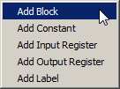 ;
; - press and hold down the left mouse button on the block in the functional blocks panel, «drag and drop» it in the diagram editor workspace then release the left mouse button. During dragging a block image will be added to the cursor icon.
For example:
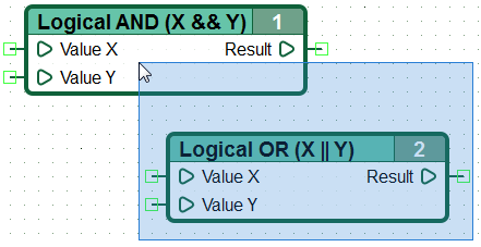
| - the mouse cursor, adding a block "Logical AND": |
Moving functional blocks
Moving functional blocks located in the diagram editor workspace is performed by "dragging": вhighlight a block, located in the diagram workspace by clicking the left mouse button (when you select the background color of the block turns yellow), and holding down the mouse button, move the mouse pointer. To complete block relocation release the left mouse button. In the same way, you can exercise a simultaneous relocation of multiple elements on the diagram by group highlighting.
Selecting elements of functional diagram
Select multiple items on the diagram is possible by "frame" - by clicking the left mouse button on the diagram area free from elements and dragging the mouse without releasing the left button, until all the elements to be captured would be in selection area. Even a partial hit of a diagram element by the "frame" leading to its selection.
Selecting multiple objects can also be performed using the method of highlighting with the mouse pointer while holding down the «Ctrl» key . Pressing again the left mouse button on the selected element by holding down the «Ctrl» button will lead to its exclusion from selected group.
Clear blocks selection is executed by clicking the left mouse button on an area of diagram workspace free from elements.
Deleting functional diagram elements
Removing functional blocks or diagram networks is performed by highlighting object or group of objects to be deleted, and pressing the «Delete» key on the keyboard, or by selecting «Delete» from context menu, calling of wich is performed by pressing the right mouse button on the selected diagram element.
Creating a connection line
Create a new connecting line on the functional diagram, may:
- from the output of one to the input of the same or another function block;
- from the output of one to the output of the same or another function block;
- from the input or output to the functional block to already existing line;
- from constant output to function block input or output or to an existing line.
In addition, starting the construction of the line, it is possible to end it at any point free of the diagram elements setting the final node, thus forming "unconnected" line.
To begin building a connection line is necessary to hover the mouse pointer to the point of the expected start of the line, press and release the left mouse button.
After the start of mouse pointer moving on the editor working area it will begin drawing connecting line, automatically adding line turn, depending on the current position of the mouse pointer.
Adding a line node (kink point) or end line at the point of its final connection is made by clicking the left mouse button.
Break the line at an arbitrary point on the diagram is possible by double clicking the left mouse button at this point, to cancel the line building - by pressing the Esc button.
Unfinished line ends with "intellectual" arrow that points in one direction or another depending on the position of the line on the plane and whether the line is a source or receiver of data (also applies to the named networks).
Modifying connection line
Modifying position and shape of the connecting line is carried by its "drag and drop" at its straight sections.
To modify the connecting line is necessary to move the mouse pointer to the area requiring changes, press the left mouse button and holding it down, move the pointer to a new location, let go of the left mouse button.
It is possible to finish building unconnected lines - continue their creation from the final node.
For line branching, need to click on the desired node, and continue to build the line from a given point.
Segments and networks of connecting lines
When implementing the algorithm in the form of a functional diagram, the usual practice is to link the output of one function block with multiple functional blocks inputs, including their own inputs. Thus, forming branched connecting lines on the diagram. The connecting line having a zero or more branches on the functional diagram, shall henceforth call network segment. The illustration below shows the two segments.
| Note: | In accordance with the agreement adopted in the CFD language, any output of the function block can be connected a single network with multiple inputs of other blocks, or their own, but there is no input of the function block can be connected to multiple outputs. Despite the fact that the diagram editor allows you to make such connection, when you try to save, entries in the controller or running in the simulator such diagrams, CannyLab displays an error message. |
By clicking the left mouse button on the connection line belonging to any segment, entire segment will be highlighted.
Segment removal is analogically to removal of any other element of the functional diagram.
Named networks
For the working convenience with large functional diagrams, the editor provides creation of named networks: the user, at their discretion, may assign to this or that segment its own name. Visually not connected segments with the same name will be logically combined, as if they were connected visually and represented a single segment. This connection shall call the network. The network of connecting lines may consist one or more segments.
Using named networks can reduce the total length and the number of intersections of the connection lines on the diagram, visually isolate groups of blocks realizing one function. This will increase the readability of the diagram.
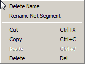
Assigning network's own name may be accomplished by double-clicking the left mouse button when pointing to a network to be named or by selecting "Rename" from context menu.
After specifying the network name in the context menu associated with it added the item 'Show Net Name' , the choice of which, at the current point to the diagram adds another inscription with the name of the network. If the network name is used in several places on the diagram, then in the context menu optionally appears items «Rename entire network» and «Select entire network».
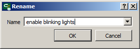
Specify the name of the network is performed using the dialog box, in the text field of which you can enter a new name, or select from a previously defined, in the current network segment. Renaming the entire network is similar.
Functional blocks identification numbers
Function blocks have unique identification numbers, which are assigned to the block when it is added to the diagram. The new block is assigned to the first available number in the range of numbers from one to the maximum number present on the block diagram, plus one.
The identification number of the block is stored in the diagram file and remains unchanged on subsequent calls to the file.
For ordering blocks numbers at any time is possible to use the option «Tools »→« Renumber blocks» of the main menu, after selecting of which, blocks will be renumbered in accordance with the order of execution, in the current diagram state.
Constants
The numerical constants can be used as inputs for function blocks. To define constants, first change the input data source of the function block by selecting «Constant» in the context menu, a call of witch is made when you hover the cursor on the block output, and pressing the right mouse button.
After that,block input appearance will change to display the associated constant. By default, the value of the newly added constant is zero.
Change the value of a constant, is possible to use the context menu, available by pressing the right mouse button on the constant.
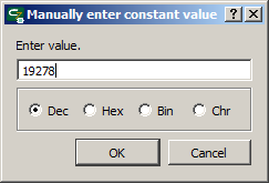
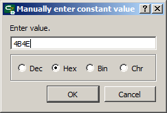
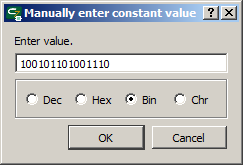
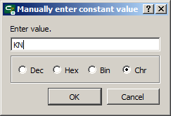
Selecting «Enter value», the user can select a constant numerical value via a dialog box.Entering values can be in decimal, hexadecimal, binary, or in symbolic form, and the display of the value entered on the diagram will be performed in the selected format.
Десятичное значение может быть задано 1..5-значным числом в интервале от 0 до 65535, шестнадцатеричное — 1..4-значным числом в интервале от 0 до FFFF (допускается вводить символы как в верхнем так и в нижнем регистре), двоичное — 1..16-значным числом в интервале от 0 до 1111111111111111, а символьное — символами основной таблицы ASCII.
| Примечание: | При вводе символьных значений допускается использование специальных символов в следующем формате: «\n» - код символа ASCII 0x0A (перевод строки), «\r» - код символа ASCII 0x0D ( возврат каретки), «\t» - код символа ASCII 0x09 (табуляция), «\0» - код символа ASCII 0x00 (ноль, пустое значение), «\xYY» любой символ, где YY – его ASCII код в шестнадцатеричном формате. |
При изменении пользователем формата отображения константы, ее текущее значение будет автоматически преобразовано в выбранную систему исчисления.
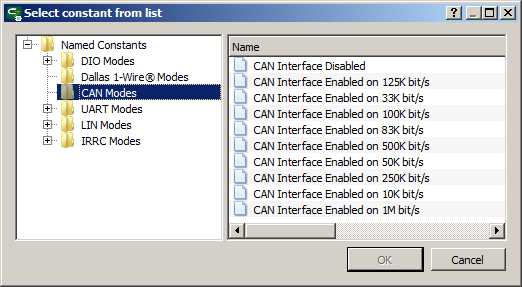
Для конфигурации и работы с ресурсами контроллера необходимо использовать специальные именованные константы, доступ к их списку производится выбором соответствующего пункта контекстного меню константы. Выбор именованной константы осуществляется в диалоговом окне.
Именованные константы представлены в виде дерева и сгруппированы по назначению.
При выборе именованной константы в качестве входного значения блока, на диаграмме вместо значения будет отображено ее сокращенное наименование.
Быстрый доступ к списку именованных констант можно получить, используя двойное нажатие левой кнопки мыши на поле константы, при удержании в нажатом состоянии клавиши «Ctrl».
| Примечание: | Несмотря на то, что каждая из именованных констант имеет вполне определенное числовое значение, использование именованных констант кроме как для конфигурации и использования связанных с ними ресурсов контроллера не желательно, так как это затруднит чтение и понимание диаграммы. |
Адреса
Доступ к аппаратным ресурсам контроллера из функциональной диаграммы производится путем обращения к определенным адресам в памяти контроллера, отображающим состояние его ресурсов и принимающим данные для управления этими ресурсами. Адреса разделены на предназначенные только для чтения или только для записи.
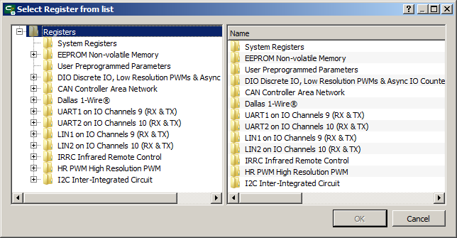
Установка адреса в качестве источника данных для входа блока выполняется аналогично заданию входной константы. После выбора адреса в качестве источника данных, открывается диалоговое окно, в котором список доступных для выбора адресов сгруппирован по функциональному назначению.
В отличие от константы, адрес нельзя ввести вручную, допускается только выбор из списка.
При выборе адреса в качестве источника или приемника данных блока, на диаграмме будет отображено его сокращенное наименование.
В отличие от константы, адрес может являться не только источником, но и приемником данных функционального блока.
Адрес, выбранный в качестве источника или приемника данных функционального блока, будет отображен на диаграмме в виде сокращенного наименования.
| Примечание: | В соответствии с соглашением принятым в языке CFD, использовать один и то-же адрес-приемник данных в нескольких элементах диаграммы не допускается. Несмотря на то, что редактор диаграмм позволяет множественное указание адресов-приемников на диаграмме, при попытке сохранения, записи в контроллер или запуске в симуляторе такой диаграммы, CannyLab выведет соответствующее сообщение об ошибке. |
По способу доступа, адреса делятся на регистры чтения и регистры записи. В качестве источника данных типа «Адрес» для функционального блока может быть использован только регистр чтения, а в качестве приемника данных типа «Адрес» - только регистр записи.
