| This documentation is out of date.
The new version of the documentation is here: https://cannylogic.com/docs |
Difference between revisions of "Output Register"
| [unchecked revision] | [unchecked revision] |
(Created page with " <div style="float:right;margin:5px;"> {|class="cannytable" width="350px" |- !colspan="2" style="background-color:#AFEEEE;"|Appearance |- |colspan="2" align="center" style="...") |
m (attached->connected) |
||
| (4 intermediate revisions by 2 users not shown) | |||
| Line 33: | Line 33: | ||
<div> | <div> | ||
| − | + | Output register is an element of the function diagram that allows the user to change the controller’s internal state or transfer information to the outside world. | |
| − | + | By using an Output register, the user can manage the controller’s resources within the function diagram, letting them potentially influence objects in the outside world. Examples include: switching an external relay; changing the electric potential at the contact of the controller that is connected to the relay coil; turning the control LED on or off; setting CAN operating mode; sending a data packet. | |
| − | + | Using most controller resources requires the user to specify their operating parameters, for example: output channel polarity, polarity and sensitivity of input channels, CAN data exchange rate etc. | |
| − | + | Refer to documentation for your specific controller model for more information. | |
</div> | </div> | ||
</div> | </div> | ||
| Line 46: | Line 46: | ||
== Features == | == Features == | ||
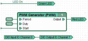
| − | + | The "Output register" element can be connected to a network, directly to a function block output or directly to the input register, thereby setting the value of a corresponding controller register that will synchronously change whenever the value of the network, function block or input register changes. | |
== Examples == | == Examples == | ||
Latest revision as of 14:40, 13 December 2020
| Appearance | |
|---|---|
| Symbol | |
| -R | |
| Group | |
| Constants and Registers | |
| Inputs | |
| -- | |
| Version CANNY Lab | |
| from 1.16 | |
Output register is an element of the function diagram that allows the user to change the controller’s internal state or transfer information to the outside world.
By using an Output register, the user can manage the controller’s resources within the function diagram, letting them potentially influence objects in the outside world. Examples include: switching an external relay; changing the electric potential at the contact of the controller that is connected to the relay coil; turning the control LED on or off; setting CAN operating mode; sending a data packet.
Using most controller resources requires the user to specify their operating parameters, for example: output channel polarity, polarity and sensitivity of input channels, CAN data exchange rate etc.
Refer to documentation for your specific controller model for more information.
Features
The "Output register" element can be connected to a network, directly to a function block output or directly to the input register, thereby setting the value of a corresponding controller register that will synchronously change whenever the value of the network, function block or input register changes.
