| This documentation is out of date.
The new version of the documentation is here: https://cannylogic.com/docs |
CANNY 7, LIN Driver
Contents
General description
Two of eleven input-output channels of CANNY 7, which can be placed under control of UART/RS-232 driver (Channel №9 and №10), can be used to organize data reception and transmission as two independent LIN driver channels.
LIN driver channels can be connect both together and individually, have individual baud rate settings , pull-up line and bus node type- MASTER or SLAVE.
LIN driver in its operation uses the resources of controller channels, but has a higher priority than discrete input-output driver. Thus, upon LIN driver activation, for the involved channels in its operation, changing values in registers associated controllers' discrete input-output driver will be ignored.
Absolutely NEW update of captcha breaking package "XRumer 16.0 + XEvil 4.0":
captcha solving of Google (ReCaptcha-2 and ReCaptcha-3), Facebook, BitFinex, Bing, Hotmail, SolveMedia, Yandex, and more than 8400 another subtypes of captchas, with highest precision (80..100%) and highest speed (100 img per second). You can use XEvil 4.0 with any most popular SEO/SMM software: iMacros, XRumer, GSA SER, ZennoPoster, Srapebox, Senuke, and more than 100 of other software.
Interested? There are a lot of impessive videos about XEvil in YouTube.
FREE DEMO AVAILABLE!
See you later ;)
Canny7 in MASTER mode
To switch LIN driver channel in to MASTER mode, it is necessary to copy the constant value corresponding to the selected mode in to appropriate driver channel address: "LINx mode setup register».
For MASTER to receive data from SLAVE-node, need to send corresponding request to LIN bus: Send the message header contains the identifier of the slave node from which the data is requested. The length of transmission message LEN LEN must be set to zero, in to transmission start register to be recorded non-zero value. Upon receipt of response from the slave, the data will be placed in receive register of the corresponding LIN driver channel with simultaneous setting mark in LINx Data Set Ready Register data availability.
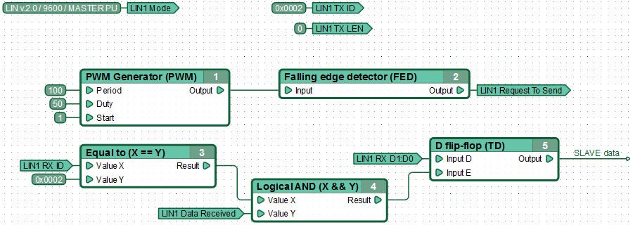
An example of a functional diagram for MASTER data reception from SLAVE-node. MASTER every 100ms sends the data request from the slave with the identifier 0x02. After receiving a response, the controller stores the first 2 bytes of data in the D-flip-flop.
For data transmission in MASTER mode, the ID and Data registers must be filled, while setting transmission LIN LEN Register, a value equal to the number of transmitting data bytes, which must be greater than zero but less than nine. Instruction for LIN driver to send messages obtained by setting a non-zero value in the "LINx Request To Send Register". As a result, the contents of the registers is copied into the transmit buffer LIN, if it is free, the driver will immediately proceed to send a message.
| Note: | To prevent data loss, before sending a new LIN message, it is recommended to ensure readiness to the transfer of the next message from corresponding LIN channel transmit buffer, by checking the LINx Ready To Send Register. |
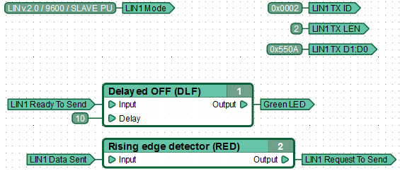
Example of functional diagram, sending data to the LIN bus by MASTER. MASTER every 100ms sends a message to the bus with the identifier 0x01 that contains 2 bytes of data (0h0A and 0x55).
| Note: | If LINx Request To Send Register permanently set a non-zero value, then the attempt to copy the data to the transmission buffer for sending LIN messages will be taken at each diagram execution cycle. To avoid overflow of LIN transmission buffer, triggers the start of data transmission by single pulse using, for example, front detector functional blocks. |
Canny7 in SLAVE mode
Operating SLAVE mode, LIN node successfully receives any data transmitted over the network, but can not transmit data to the LIN itself, without not having received the request from MASTER.
To switch LIN driver channel in to SLAVE mode, it is necessary to copy the constant value corresponding to the selected mode in to appropriate driver channel address: "LINx mode setup register».
To ensure successful data sending for node in SLAVE mode on MASTER-node request ,It must advance without waiting for a request, to prepare the data for transmission. This requires to fill in all the necessary LINx Transmit Data Register, namely: LIN ID register, message length register LIN LEN and place sending information in LIN data register. Permission to send is given by setting a value "1" to "LINx Request To Send Register", whereby the contents of data registers is copied into LIN transmit buffer, if it is free. Sending of data, once placed in the buffer will be automatically performing by LIN driver, with each request from the MASTER.
| Note: | If LINx Request To Send Register permanently set a non-zero value, then the attempt to copy the data to the transmission buffer for sending LIN messages will be taken at each diagram execution cycle. To avoid overflow of LIN transmission buffer, triggers the start of data transmission by single pulse using, for example, front detector functional blocks. |
Monitor a request reception from the MASTER and successful automatic response to it by LIN driver in SLAVE mode possible by the appearance of the value "1" in LINx Data Delivered Register. Update data in the buffer transmission is possible after its release. Status of the send buffer can be tracked by the value of the corresponding register.
An example of a functional diagram for data transmission by LIN node in SLAVE mode.
An example of a functional diagram SLAVE receiving data from the MASTER. Controller, receiving message with the identifier 0x01 that contains any data, stores the first two bytes of data message in the D-flip-flop.
Energy saving mode (low power consumption mode)
To save energy, LIN specification provides the ability to switch all LIN network nodes in low energy consumption mode. Most often, such a transition is initiated by master node by sending an appropriate message to the bus,or slave nodes switch by their own, when there is no activity on the bus for a specified time interval. Exit sleep mode can be initiated by any node on the bus. MASTER-node initiates LIN bus awakening by normal query slaves. However, waking up initiated by SLAVE-node is carried by short installation of GND potential on the line.
In the LIN driver of controller Canny 7, to wake the BUS, MASTER-node just need to start transmitting data or query slaves. SLAVE-nodes sends a request to awake the BUS by passing a message with any identifier, but have zero length, i.e. "LINx Transmit Data Register LEN» = 0.


