| This documentation is out of date.
The new version of the documentation is here: https://cannylogic.com/docs |
Difference between revisions of "CANNY 7, LIN Driver"
| [unchecked revision] | [unchecked revision] |
(→Driver registers) |
(→Работа контроллера в режиме MASTER) |
||
| Line 333: | Line 333: | ||
|} | |} | ||
| − | === | + | === Canny7 in MASTER mode === |
| − | + | To switch LIN driver channel in to MASTER mode, it is necessary to copy the constant value corresponding to the selected mode in to appropriate driver channel address: "LINx mode setup register». | |
| − | + | For MASTER to receive data from SLAVE-node, need to send corresponding request to LIN bus: Send the message header contains the identifier of the slave node from which the data is requested. The length of transmission message LEN LEN must be set to zero, in to transmission start register to be recorded non-zero value. Upon receipt of response from the slave, the data will be placed in receive register of the corresponding LIN driver channel with simultaneous setting mark in LINx Data Set Ready Register data availability. | |
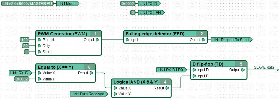
| − | + | An example of a functional diagram for MASTER data reception from SLAVE-node. MASTER every 100ms sends the data request from the slave with the identifier 0x02. After receiving a response, the controller stores the first 2 bytes of data in the D-flip-flop. | |
[[File:6_10_4_1.png|center|950px]] | [[File:6_10_4_1.png|center|950px]] | ||
| − | + | For data transmission in MASTER mode, the ID and Data registers must be filled, while setting transmission LIN LEN Register, a value equal to the number of transmitting data bytes, which must be greater than zero but less than nine. Instruction for LIN driver to send messages obtained by setting a non-zero value in the "LINx Request To Send Register". As a result, the contents of the registers is copied into the transmit buffer LIN, if it is free, the driver will immediately proceed to send a message. | |
{| | {| | ||
| − | |valign="top" style="padding-left:0.5em;"|'' | + | |valign="top" style="padding-left:0.5em;"|''Note:'' |
| − | |valign="top" style="padding-left:0.5em;"|'' | + | |valign="top" style="padding-left:0.5em;"|''To prevent data loss, before sending a new LIN message, it is recommended to ensure readiness to the transfer of the next message from corresponding LIN channel transmit buffer, by checking the LINx Ready To Send Register.'' |
|} | |} | ||
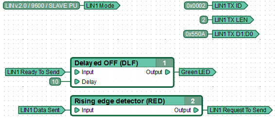
| − | + | Example of functional diagram, sending data to the LIN bus by MASTER. | |
| + | MASTER every 100ms sends a message to the bus with the identifier 0x01 that contains 2 bytes of data (0h0A and 0x55). | ||
[[File:6_10_4_2.png|center|800px]] | [[File:6_10_4_2.png|center|800px]] | ||
{| | {| | ||
| − | |valign="top" style="padding-left:0.5em;"|'' | + | |valign="top" style="padding-left:0.5em;"|''Note:'' |
| − | |valign="top" style="padding-left:0.5em;"|'' | + | |valign="top" style="padding-left:0.5em;"|''If in LINx Request To Send Register permanently set a non-zero value, then the attempt to copy the data to the transmission buffer for sending LIN messages will be taken at each diagram execution cycle. To avoid overflow of LIN transmission buffer, triggers the start of data transmission by single pulse using, for example, front detector functional blocks.'' |
|} | |} | ||
Revision as of 05:49, 27 January 2016
Contents
General description
Two of eleven input-output channels of CANNY 7, which can be placed under control of UART/RS-232 driver (Channel №9 and №10), can be used to organize data reception and transmission as two independent LIN driver channels.
LIN driver channels can be connect both together and individually, have individual baud rate settings , pull-up line and bus node type- MASTER or SLAVE.
LIN driver in its operation uses the resources of controller channels, but has a higher priority than discrete input-output driver. Thus, upon LIN driver activation, for the involved channels in its operation, changing values in registers associated controllers' discrete input-output driver will be ignored.
Driver registers
The following describes the acceptable LIN driver operation control registers values.
LIN driver configuration Registers allows to set up the controller as a LIN bus node:
| Address | Expected values | ||||||||
|---|---|---|---|---|---|---|---|---|---|
|
|
Channel configuration for operation in this mode is determined by a constant, which is a combination of parameters: protocol version , baud rate, operation mode and the availability of internal channel pull-up.
| Parameter | The list of acceptable values |
|---|---|
| LIN protocol version | 1.3; 2.0 |
| baud rate | 2400; 9600; 19200 |
| Operation mode | MASTER; SLAVE |
| Pull-up | plus; float |
Named constants that represent LIN configuration parameters combination, available to the user in the "LIN Modes" CannyLab constants directory, which can be accessed via function block entry context menu having "constant" type.
LIN driver diagnostic registers.
| Address | Return Values | ||||||||
|---|---|---|---|---|---|---|---|---|---|
|
| ||||||||
|
| ||||||||
|
| ||||||||
|
|
LIN Receive Registers.
| Address | Return Values | |||||||||
|---|---|---|---|---|---|---|---|---|---|---|
|
| |||||||||
|
| |||||||||
|
| |||||||||
|
| |||||||||
|
|
| Note: | LIN Received Data Register ID displays only the lower 6 bits of the identifier: 4-bit address of the device and the 2- bits used in the LIN 1.1 to encode the message length, and later to expand the address. 10 higher bits of LIN received message ID register always zero. |
LIN transmit registers.
| Адрес | Expected Values | |||||||||
|---|---|---|---|---|---|---|---|---|---|---|
|
| |||||||||
|
| |||||||||
|
| |||||||||
|
|
| Note: | When sending LIN-messages, the driver discards all but the lower 6 bits of LIN ID register, automatically generates two parity bits and complements them ID, according to requirements of the standard. |
| Note: | When working with LIN networks versions below 1.3, be careful in the formation of outgoing messages. The driver allows the use of combinations of length and identifier transmitting message unacceptable in this standard. |
Canny7 in MASTER mode
To switch LIN driver channel in to MASTER mode, it is necessary to copy the constant value corresponding to the selected mode in to appropriate driver channel address: "LINx mode setup register».
For MASTER to receive data from SLAVE-node, need to send corresponding request to LIN bus: Send the message header contains the identifier of the slave node from which the data is requested. The length of transmission message LEN LEN must be set to zero, in to transmission start register to be recorded non-zero value. Upon receipt of response from the slave, the data will be placed in receive register of the corresponding LIN driver channel with simultaneous setting mark in LINx Data Set Ready Register data availability.
An example of a functional diagram for MASTER data reception from SLAVE-node. MASTER every 100ms sends the data request from the slave with the identifier 0x02. After receiving a response, the controller stores the first 2 bytes of data in the D-flip-flop.
For data transmission in MASTER mode, the ID and Data registers must be filled, while setting transmission LIN LEN Register, a value equal to the number of transmitting data bytes, which must be greater than zero but less than nine. Instruction for LIN driver to send messages obtained by setting a non-zero value in the "LINx Request To Send Register". As a result, the contents of the registers is copied into the transmit buffer LIN, if it is free, the driver will immediately proceed to send a message.
| Note: | To prevent data loss, before sending a new LIN message, it is recommended to ensure readiness to the transfer of the next message from corresponding LIN channel transmit buffer, by checking the LINx Ready To Send Register. |
Example of functional diagram, sending data to the LIN bus by MASTER. MASTER every 100ms sends a message to the bus with the identifier 0x01 that contains 2 bytes of data (0h0A and 0x55).
| Note: | If in LINx Request To Send Register permanently set a non-zero value, then the attempt to copy the data to the transmission buffer for sending LIN messages will be taken at each diagram execution cycle. To avoid overflow of LIN transmission buffer, triggers the start of data transmission by single pulse using, for example, front detector functional blocks. |
Работа контроллера в режиме SLAVE
Работая в режиме SLAVE, узел сети LIN успешно принимает любые данные передаваемые по сети, но не может сам передавать данные в LIN, не получив на то соответствующего запроса от MASTER.
Для перевода канала контроллера в режим SLAVE, необходимо в соответствующий каналу адрес «Регистр конфигурации LINx» скопировать значение константы, соответствующей выбранному режиму работы.
Для обеспечения успешной отправки данных узлом находящемся в режиме SLAVE по запросу MASTER-узла, необходимо заранее, не дожидаясь запроса, подготовить данные к передаче. Для этого необходимо заполнить все необходимые регистры сообщения передачи драйвера LIN, а именно: регистр идентификатора LIN ID, регистр длины сообщения LIN LEN и разместить передаваемую информацию в регистрах данных LIN. Разрешение на отправку сообщения дается путем установки значения «1» в «Регистр начала передачи сообщения LINх», в результате чего содержимое регистров данных копируется в буфер передачи LIN-сообщения, если он свободен. Отправка однажды помещенных в буфер передачи данных будет выполняться драйвером автоматически, при каждом получении запроса от MASTERа.
| Примечание: | Если в регистре начала передачи сообщения LINх постоянно установлено ненулевое значение, то попытки копирования данных в буфер передачи для отправки сообщения LIN будут предприниматься на каждом цикле выполнения диаграммы. Во избежание переполнения буфера передачи LIN инициируйте начало передачи данных единичным импульсом, используя, например, функциональные блоки детекторов фронта. |
Контролировать поступление запроса от MASTER и успешную отправку автоматического ответа на него драйвером узла находящегося в режиме SLAVE можно по появлению значения «1» в Регистре успешной отправки данных драйвера LINx. Обновлять данные находящиеся в буфере передачи возможно после его освобождения. Состояние буфера передачи можно отслеживать по значению соответствующего регистра драйвера.
Пример функциональной диаграммы передачи данных LIN узлом в режиме SLAVE.
Пример функциональной диаграммы получения SLAVEом данных от ведущего устройства. Получая сообщение с идентификатором 0х01, содержащее какие-либо данные, контроллер сохраняет первые два байта данных сообщения в D-триггере.


