| This documentation is out of date.
The new version of the documentation is here: https://cannylogic.com/docs |
CANNY 7, Discrete IO Driver
Contents
Genegal Description
Users CANNY 7 has eleven discrete input-output general purpose channels available. Each channel is physically presented to the appropriate pins of connector X2 or X3. Writing and reading data of the respective drivers registers, the functional diagram can manage the electric potential in each of these contacts and get information about current value of potential on each of them.
Channels physical characteristics allows to connect to them a variety of external actuators - electromagnetic relays, small motors, LEDs. As an external digital input signals it is possible to use a mechanical, electromechanical, and electronic buttons and switches, pulse generators, voltage source 0-12V and transistor outputs of various equipment , etc.
Channels operation mode and parameters specified by function diagram. At any given time, the channel can only work in one of the possible modes, but it is possible to dynamic override the channel configuration from the functional diagram during execution.
A number of CANNY 7 controller drivers, specifically High Resolution PWM, UART / RS232 / Modbus, LIN, I²C, Dallas® 1-Wire® и Infrared Remote Control Driver, in their operation use input-output channels resources and, thus, have a higher priority. Thus, when using these drivers of certain channel controller, IO driver access to these channels is not possible.
IO Registers
The parameters defining operation mode and channel current state, are set for each channel independently. Below is acceptable values specifications of registers controlling input-output channels operation in all major modes.
| Address | Expected values | |||||||||||||||||||||||||||||||||||
|---|---|---|---|---|---|---|---|---|---|---|---|---|---|---|---|---|---|---|---|---|---|---|---|---|---|---|---|---|---|---|---|---|---|---|---|---|
|
| |||||||||||||||||||||||||||||||||||
|
| |||||||||||||||||||||||||||||||||||
|
|
Registers control IO channels driver are divided into containing information of the IO driver altogether and containing information about the state of each channel individually. The following describes registers control driver return values of IO channels in all major operation modes.
| Address | Return values | |||||||||||||||||||||||||||||
|---|---|---|---|---|---|---|---|---|---|---|---|---|---|---|---|---|---|---|---|---|---|---|---|---|---|---|---|---|---|---|
| DIO Input Activity Detect Register |
| |||||||||||||||||||||||||||||
| DIO Output Overload Register |
| |||||||||||||||||||||||||||||
|
|
Channel neutral state
The channels are automatically transferred to a neutral state in the following cases:
- when controller is operating in software download mode;
- when the controller is in standalone mode, if the channel configuration is not set, given the constant "Neutral state" or "0";
- at the time of controller software reset or power-on reset , before switching to a stand-alone mode and start functional diagram execution;
- in the event of controller malfunction or system software failure.
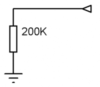
Electrically, channel neutral position - "air", is equivalent to a high resistance output, internally connected to the the GND terminal with resistor ~ 200k Ohm.
Digital output mode
The channel configured to operate as a discrete output, sets at the appropriate controller pin, an electric potential, corresponding to the "ON" state, when writing a nonzero value to the address of channel output value register, and sets at the appropriate controller pin,an electric potential corresponding to the "OFF" state when recording the value of "0 " to the address of channel output value register.
Channel configuration for operation in this mode is determined by a constant, defining combination of parameters, that determine the electrical potential and current at the terminal of the corresponding controller channel in the "ON" and "OFF" position.
| Parameter | Acceptable values |
|---|---|
| Channel type | Digital output. |
| "ON" | plus (1mA); PLUS (100mA); minus (1mA); MINUS (100mA);air. |
| "OFF" | plus (1mA); PLUS (100mA); minus (1mA); MINUS (100mA);air. |
Named constants that represent channels configuration parameters combination available to the user, contains in the "DIO Channel Configuration" CannyLab constants directory, which can be accessed via function block entry context menu having a type of "constant".
To transfer controller channel in to digital output mode, it's necessary to copy the constant value corresponding to the selected mode in to corresponding channel address "Register channel configuration №**"
| Note: | For channels operating in the digital output configuration, it is also possible to obtain a value, corresponding to the actual current electrical potential at the channel terminal, which allows the use of channel feedback mode |
An example of a functional diagram performing every second, alternate switching of electrical potentials from + 12V (100mA) to GND (1 mA) at controller terminals, corresponding to channels #0 & #1.
PWM output mode
The channel configured for operation in PWM output, generates on the corresponding controller pin a pulse width signal of a predetermined polarity, frequency, and duty cycle. In this mode, the channel is asynchronous to functional diagram, which allows for greater stability of generated timing signal, than in the organization of PWM generator by functional diagram resources.
Channel configuration for operation in this mode is determined by a constant, representing a combination of parameters that determine the electrical potential and current to the terminal in the active "ON" and passive "OFF" generating phase, corresponding channel of the controller, and a pair of numeric values defining the frequency and filling generating pulses in milliseconds.
| Parameter | Acceptable values |
|---|---|
| Channel type | PWM output. |
| "ON" | plus (1mA); PLUS (100mA); minus (1mA); MINUS (100mA);air. |
| "OFF" | plus (1mA); PLUS (100mA); minus (1mA); MINUS (100mA);air. |
Named constants that represent channels configuration parameters combination available to the user, contains in the "DIO Channel Configuration" CannyLab constants directory, which can be accessed via function block entry context menu having a type of "constant".
To transfer controller channel in to PWM output mode it is necessary:
- to copy value constant, corresponding to the selected mode into selected channel address "DIO Mode IO Channel ##";
- to copy digital value 0 to 65565, setting generated pulses period in ms into selected channel address "DIO Period IO Channel ##" ;
- to copy digital value 0 to 65565, setting generated pulses duty cycle in ms into selected channel address "DIO Output IO Channel ##" ;
An example of a functional diagram performing every second, alternate switching of electrical potentials from + 12V (100mA) to GND (1 mA) at controller terminal, corresponding to channel #0.
Режим дискретного входа
Канал, сконфигурированный для работы в режиме дискретного входа, возвращает значение «1» в регистре своего входного значения, если на соответствующем контакте контроллера установился электрический потенциал соответствующий состоянию «Полярность входа»; и возвращает значение «0» в регистре входного значения, когда на соответствующем контакте контроллера установился электрический потенциал не соответствующий состоянию «Полярность входа».
Конфигурация канала для работы в данном режиме, определяется константой, представляющей комбинацию параметров, определяющих электрический потенциал на контакте принимаемый за состояние «1» соответствующего канала контроллера, наличие и потенциал внутренней «подтяжки» контакта контроллера, чувствительность и активность канала в режиме пониженного энергопотребления контроллера.
| Параметр | Перечень допустимых значений |
|---|---|
| Тип канала | Дискретный вход. |
| Полярность входа | ПЛЮС; МИНУС. |
| Подтяжка | плюс; минус; воздух. |
| Режим ожидания | активный; пассивный. |
| Чувствительность | максимум (0 мс); высокая (20 мс); норма (200 мс); низкая (700 мс). |
Изменение потенциала на контакте канала, находящегося в режиме активного ожидания, приведет к немедленному автоматическому выходу контроллера из режима пониженного энергопотребления. Изменение потенциала на контакте канала, находящегося в режиме пассивного ожидания, не повлияет на режим энергопотребления контроллера.
Чувствительность канала определяет его «защиту от дребезга», т.е. задает временной интервал, в течение которого электрический потенциал на соответствующем каналу контакте контроллера должен оставаться неизменным, для того чтобы считаться установившимся и изменить состояние регистра входного значения канала.
Именованные константы, представляющие доступные пользователю комбинации параметров конфигурации каналов, содержатся в разделе «Конфигурация каналов ввода-вывода» справочника констант CannyLab, доступ к которому осуществляется через контекстное меню входа функционального блока, имеющего тип «Константа».
Для перевода канала контроллера в режим дискретного входа, необходимо в соответствующий каналу адрес «Регистр конфигурации канала №ХХ» скопировать значение константы, соответствующей выбранному режиму работы. Пример функциональной диаграммы, включающей встроенный зеленый светодиод контроллера при поступлении и удержании в течение не менее 200мс на соответствующем каналу №0 контакте контроллера, потенциала GND:
Режим счетчика
Канал сконфигурированный для работы в режиме счетчика, возвращает в регистре своего выходного значения число, соответствующее количеству переключений электрического потенциала на соответствующем контакте контроллера из состояния противоположного параметру «Полярность входа» в состояние соответствующее параметру «Полярность входа» за прошедший период времени заданной продолжительности. Таким образом, канал в данном режиме исполняет функцию счетчика передних фронтов сигнала или частотомера.
В данном режиме канал работает асинхронно функциональной диаграмме, что позволяет добиться большей точности определения временных параметров исследуемого сигнала и измерять сигнал большей частоты, чем при организации счетчика импульсов средствами функциональной диаграммы.
Конфигурация канала для работы в данном режиме, определяется константой, представляющей комбинацию параметров, определяющих электрический потенциал, при появлении которого на контакте соответствующего канала контроллера регистрируется передний фронт сигнала, наличие и потенциал внутренней «подтяжки» контакта контроллера.
Конфигурация канала для работы в данном режиме задается комбинацией следующих параметров:
| Параметр | Перечень допустимых значений |
|---|---|
| Тип канала | Вход-счетчик. |
| Полярность входа | ПЛЮС; МИНУС. |
| Подтяжка | плюс; минус; воздух. |
В режиме счетчика, канал всегда находится в активном ожидании с максимальной чувствительностью. Подсчет драйвером числа изменений состояния такого канала ведется асинхронно.
Именованные константы, представляющие доступные пользователю комбинации параметров конфигурации каналов, содержатся в разделе «Конфигурация каналов ввода-вывода» справочника констант CannyLab, доступ к которому осуществляется через контекстное меню входа функционального блока, имеющего тип «Константа».
Для перевода канала контроллера в режим входа-счетчика, необходимо:
- в соответствующий каналу адрес «Регистр конфигурации канала №ХХ» скопировать значение константы, соответствующей выбранному режиму работы;
- в соответствующий каналу адрес «Регистр периода канала №ХХ» скопировать числовое значение от 0 до 65565, устанавливающее период подсчета импульсов в мс;
При ненулевом значении в регистре периода, значение в регистре входного значения канала обновляется один раз в период и содержит число импульсов зарегистрированное счетчиком за прошедший период.
Подсчет счетчиком импульсов ведется с переполнением. Это означает, что при достижении значения 65565 и последующем увеличении на единицу, значение счетчика устанавливается равным нулю, но каждый последующий импульс вновь увеличивает значение счетчика на единицу.
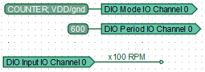
Пример функциональной диаграммы тахометра с разрешающей способностью 100 оборотов в минуту, подсчитывающем число импульсов на соответствующем каналу №0 контакте контроллера:
| Примечание: | Если период установлен равным нулю, то счетчик непрерывно ведет подсчет импульсов с накоплением результата в регистре выходного значения канала. В данном режиме значение, этого регистра сбрасывается лишь в результате переполнения регистра. |
Equivalent circuit diagrams
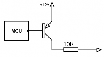
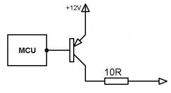
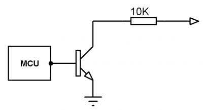
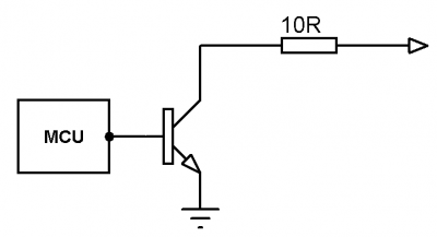
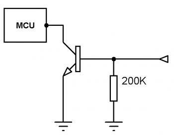
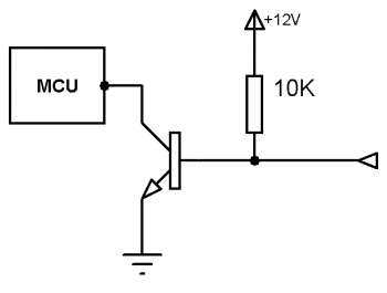
Equivalent circuit diagrams for each possible state of the input-output channel shown in the table below:
| Channel state | Equivalent circuit diagram |
|---|---|
| «air» | |
| «plus (1mA)» | |
| «PLUS (100mA)» | |
| «minus (1mA)» | |
| «MINUS (100mA)» | |
| «pull up air» | |
| «pull up plus» | |
| «pull up minus» |
Electrical protection
For channels operated in a digital output and PWM output modes, whose current in "ON" or "OFF" state significantly exceeds 100 mA, controller system software performs automatic short circuit protection. Protection implemented as the form of switching of a shorted channel into the neutral mode, the subsequent periodic pulse of start test and reset to a user-defined configuration upon detection elimination of short circuit. This protection is fully automatic and requires no user configuration.


