| This documentation is out of date.
The new version of the documentation is here: https://cannylogic.com/docs |
CANNY 7
CANNY 7 — miniature programmable logic controller designed for automotive, domestic and industrial use.
Contents
General Information
Due to limited external channels, programmable logic controller CANNY7 may be attributed to a class of smart relays or Nano PLC. CANNY7 is capable of solving many automation, controlling and monitoring tasks.
CANNY7 is the first programmable logic controller oriented for automotive applications, with the following unique features and combination:
- rated power supply and IO channels voltage 0 / 12V (18V max);
- the maximum output current of each of the 11 IO channels +/- 120mA, sufficient to control usual automotive relay;
- CAN 2.0B Interface, compliant with ISO-11898, SAE J2411 widely used in modern cars;
- built-in energy consumption management in the range of 5 to 60 mA, helps to conserve battery power during period of inactivity in a car;
- EEPROM for applications and sixty-four 16-bit non-volatile memory data cells, available to user application to preserve critical data during a power failure;
- wide operating temperature ranged from -40 to + 85 ° C;
- Integrated surge protection and short circuit protection
- compact housing compliant to IP50 enclosure protection specification, suitable for installation and operation as part of a car cabin equipment;
- specialised packages of system and application software to use with automotive CAN and LIN networks.
To develop custom software for CANNY7, use graphical programming language CFD to quickly create user-effective applications- Functional Diagrams. Free IDE CannyLab contains tools for editing, debugging and writing software to the controller.
Requirements for writing software to the controller:
- PC with a USB port version 1.1 or higher
- Installed CannyLab environment
- Ordinary miniUSB cable
Controllers' memory acessible to user is enough to accommodate the program, consisting of several hundred functional blocks, which allows for fairly sophisticated algorithms. Each of the 11 IO channels are able to operate in any of the 98 modes that define the voltage, current, and temporal parameters of the input and output signals. In addition, some of the channels can be configured to operate in digital mode, to transmit / receive data of such protocols as 1-Wire, I2C, RS-232, LIN, CAN. The configuration of each channel can be set and adjusted from the user application. Two-coloured LEDs, controlled from the user application, are useful to indicate controller or debugging mode.
Design and functional operation
The appearance and layout
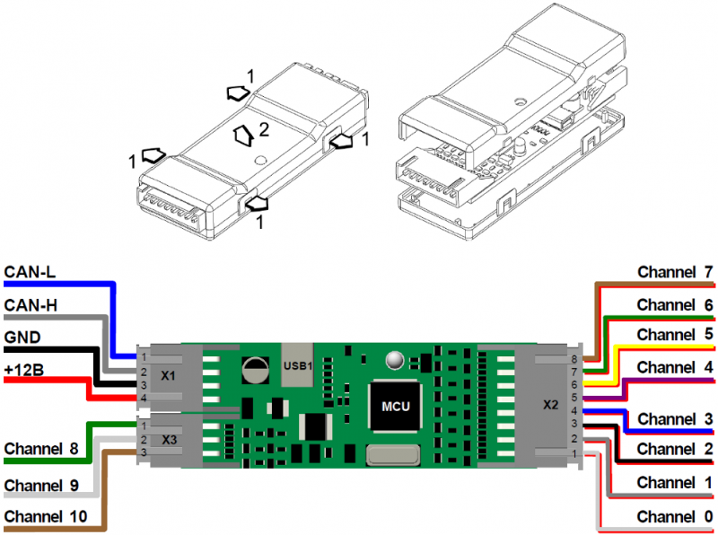
The main components of CANNY 7 are: a micro controller (MCU) with the auxiliary circuits, power supply system for all controllers' elements, IO channels level matching circuit, electric protection system, connectors and LED, based on a single print board 65 x 23 mm mounted inside a quick-open plastic casing. The controller has three external connectors and one internal. To connect the controller to the power supply and external devices, the kit includes a set of jumper harness.
- External connector X1 contains four terminals: + 12V input, power input GND, CAN-H and CAN-L.
- External connector X2 contains eight terminals, corresponding to the first eight channels of the controller, from №0 to №7.
- External connector X3 has three terminals, channels accordingly- №8, №9 and №10. Internal connector USB1 is to connect controller to the PC with miniUSB cable.
Software Architecture
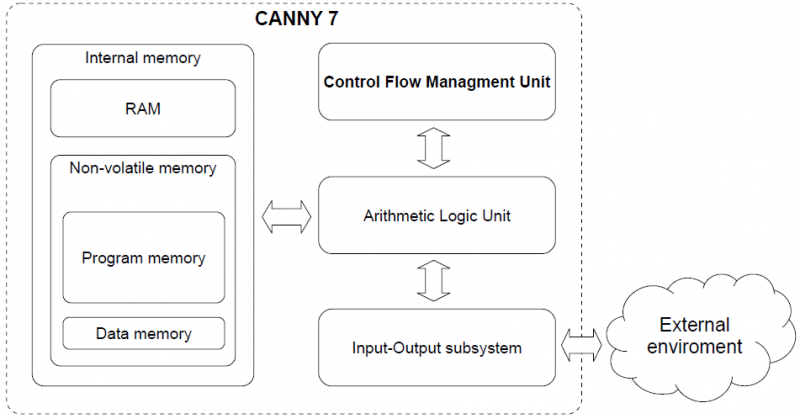
CANNY 7 is a digital programmable computing control device. CANNY 7 main elements are: arithmetic logic unit (ALU), internal memory, commands execution management subsystem and input-output system.
Arithmetic Logic Unit is the processing core of CANNY 7. ALU provides system software and user functional execution diagram placed into the internal memory of the controller. Controller's internal memory is divided into the EEP program memory, EEP data memory, and ROM. The command's management subsystem is responsible for switching and setting mode of the controller. The IO system provides controllers' communication to the outside world, using both discrete IO channels and standard digital interfaces CAN / LIN / RS232 / USB.
Software Structure
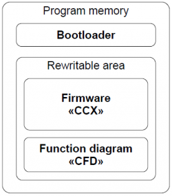
Software CANNY 7 consists of: a software loader, system software (operating system and driver), and a custom function diagram.
The program loader provides the controller with the software download mode, organising data transmission between CANNY 7 and PC using USB protocol. It checks the data integrity transmitted from the PC and loading to the controllers' internal memory. The software loader placed into the internal memory of the controller during production and can not be deleted or modified by the user. The manufacturer distributes CANNY 7 system software in CCX file format. It includes an operating system and a set of drivers providing function diagram execution and its interaction with the controllers' resources. User is restricted to modify system data file. The contents of various PCX files can be reloaded into the controller by user.
Custom block diagram is created and modified in integrated development environment CannyLab, then it can be loaded into the controller where it specifies the algorithm to work standalone or saved in to CFD file.
Operation modes
There are several operation modes to perform basic operations with controller.
Software download mode
In this mode, the controller is running boot loader to load system software, and functional blocks under CannyLab management. Controller switch to this mode automatically when connected to PC with USB cable. During the transition to SW download mode the controller performs a master reset: the functional diagram execution stops, IO channels are switching to neutral state, built-in green LED turns on. When controller establishes communicating with the PC software, the green LED goes into a flickering mode. Exit from this mode happens automatically when the connection to the PC is disrupted. If at the end of the software download mode , EEPROM have system software loaded correctly, the controller will switch to standalone mode, otherwise it returns to the download mode.
Autonomous mode
Standalone mode is the main controllers' mode. In this mode, the controller is running continuously under system software sequence, in an endless cycle, performing the functional diagram, working on the algorithm specified by the user. Transition to this mode takes place automatically when the controller is connected to an external 12V power supply and the absence of the USB connection. When operating in this mode, the functional diagram has access to all resources of the controller and drivers included in the system software when loaded.
Sleep mode
This mode is an option of normal standalone mode in which, after each cycle of execution of a function diagram, the controller pauses to reduce its power consumption to a minimum. Thus, the controller operates in a pulsed mode, periodically "asleep" and "waking up". Enable, disable, and configure the parameters of this mode are controlled by the functional diagram. Using this mode is relevant when developing systems, focused on battery-power, such as the on-board car equipment.
Runtime Environment
Functional diagram presentation
The graphical block diagram developed in CannyLab environment, automatically processed by the translator just before loading to the controller. CannyLab checks on the consistency of the diagram, determines function blocks execution order and converts the diagram into the executable code - a sequence of machine instructions CANNY 7 controllers' ALU.
The execution order
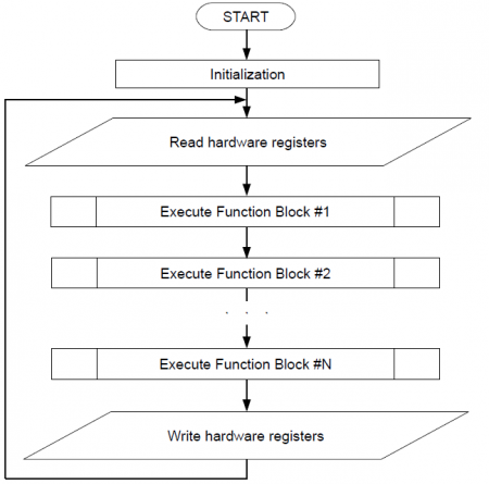
Executable program code during loading into the controller already contained system software, is including in the sequence of the system software machine instructions. Thus, the aggregate command sequence loaded with system software and functional diagram, will be: initialisation routines executed once after each controllers' reset and executable functional diagram code, framed with the controller resources' procedure management, and placed in an infinite executable loop - diagrams running loop. Some of the drivers included in the controller system software, such as CAN driver, require controller to raise immediate response during data transmission and reception of program events. Program code of these drivers asynchronously processed by the controller in parallel with the main execution flow. In the processing of asynchronous drivers calls, the diagrams main run loop performance is briefly suspended.
Access to hardware resources
All available resources to the user from the functional diagram : the system resources of the controller, IO subsystem and additional drivers included in the system software, appears on a controllers' internal memory protected address space. This address space is divided into read registers (control) and recording registers.
The user is able to specify the reading register address as a source of input data from virtually any function block of a diagram. Thereby extract and use to implement their own algorithms, data received by the controller from the outside world. For example information about the electric potential on any controllers' terminal, or the data packet contents received from the CAN bus. Recording register address can be used as the output recipient for any functional block on the diagram.Thus, the user controls the resources of the controller from functional diagrams which gives an opportunity to influence the objects of the outside world. For example: switch external relay by changing the electrical potential on one of the pins of the controller, turn LED on; set CAN operation mode; send a data packet.
The most resources used includes assignment required operating parameters, such as the polarity of the output channels, the polarity and the sensitivity of the input channels, CAN communication speed and so on.
Specifying these parameters is made in the form of recording specific constants in one or a few specific registers, depending on а required set of resources configuration. For example, copying a constant with a value of 121 in the register located at 2432 address is set channel №0 to an output positive polarity mode.
In CannyLab environment, for user convenience, all the of the controllers' available registers are named, as well as all special constants that are used in interaction with the controllers' resources. Therefore, for CannyLab user this operation will look as setting the constants named "standard positive output" at the input of the function block "Copy" and setting the address with the name "channel №0 configuration register» at its output.
Having thus established channel №0 mode, by the appearance of the value "1" in the register located at 2465 address ("channel №0 input value register"), we can learn about the application of a positive electric potential to №1 terminal of X2 connector.
System Registers
System Registers
- Main article: CANNY 7, System Registers
System resources are divided into an address group of read registers and an address group of write registers. Referring to the given registers from the functional diagram, you can get demanding information for practical application about the current status of the controller, and control its operation mode. The list of system resources registers located in the "State of the controller" addresses directory CannyLab, which is available to the user via IO context menu "Address" type of the function blocks.
Discrete Inputs and Outputs
- Main article: CANNY 7, Discrete IO Driver
CANNY 7 users have access to eleven discrete general purpose IO channels . Each channel is physically available through corresponding pins of X2 and X3 connectors . Writing and reading data of the respective drivers registers , the functional diagram can manage the electric potential in each of these contacts and getting information about the current potential of each of them. The channel physical characteristics allow connection to a variety of external actuators such as: electromagnetic relays, small motors, LEDs. As an external digital input signal, it is possible to use a mechanical, electromechanical, and electronic buttons and switches, pulse generators, voltage source 0-12V and transistor outputs of various equipment , etc.
Channels operation mode and parameters specified by function diagram. At any given time, the channel can only work in one of the possible modes, but it is possible to dynamic override the channel configuration from the functional diagram in the process of its execution.
High Resolution PWM
- Main article: CANNY 7, HR PWM Driver
Two of the eleven IO channels (Channel №1 and №2) CANNY 7 are able to work in high-resolution pulse-width modulator mode. The channels may be activated independently of each other and have a configuration independent duty cycle and line pull-up, however, the high-resolution PWM period is a common parameter to both channels. In HR PWM mode, the PWM timing parameters - the period and duty cycle are set in the range of from 2 to 20,000 microseconds, in 1 microsecond increments.
HR PWM channel has a fixed pulse polarity - GND 100mA. Generation can be conducted in either open collector (no pull-up or external pull-up) or with the internal pull-up to +12V (specified by setting value in the appropriate register ). In this mode, the channel is asynchronous to functional diagram, which allows for maximum stability of generated signal timing parameters.
| Note: | In the high-resolution pulse width modulator the electrical short circuit protection is disabled! Overload or channels short circuit being in RF PWM mode can cause damage to controller! |
UART / RS232 / Modbus driver
- Main article: CANNY 7, UART Driver
Two of eleven IO channels (#9 and #10) CANNY 7 supports UART, RS-232 serial protocols data transmission/reception. It may be used to connect the controllers with each other or with external equipment supporting this communications protocols. The channels may be activated independently of each other and have individual data speed setting, protocol type and configuration, pull up line.
UART implementation in CANNY 7 controllers allows to organize serial data reception and transmission over a single wire in half-duplex mode. Thus CANNY7 may have two independent connections using the UART protocol. Monitoring of the data link status should be done from the functional diagram. If the channel is free, the device may start data transmitting , otherwise the device should wait for the line release.
RS-232 implementation by using both UART data channels , allows to exchange data with other RS-232 device in a duplex mode, i.e. one channel to perform data sending and on the other to simultaneously receive data.
Modbus protocol in CANNY7 controllers implemented as over UART as over RS-232. As ADU (Application Data Unit) used compact binary option Modbus RTU. Checking the data integrity carried out by automatically calculated checksum (CRC). Package size is limited to 16 bytes including the CRC.
| Note: | For correct operation of all protocols based on the UART / RS-232 requires that all GND terminals of the devices committing communication, were given to a single potential ("common ground"). |
| Note: | In UART implementation-active line is the potential GND 100mA, passive - positive potential of a given internal or external channel pull-up. In implementing RS-232 - the potentials inverse. |
Driver UART/RS-232/Modbus operates using controllers' channels resources, but has a higher priority than a discrete input-output driver. Thus, upon activation of UART/RS-232/Modbus driver, for channels involved in its operation, a value changes in registers associated with discrete input-output driver, will be ignored.
CAN driver
- Main article: CANNY 7, CAN Driver
Two special external terminals of CANNY 7 controller, located on the 4 pin connector: CAN-H and CAN-L, designed for connection to digital information CAN-bus.
LIN driver
- Main article: CANNY 7, LIN Driver
Two of eleven input-output channels of CANNY 7, which can be placed under control of UART/RS-232 driver (Channel №9 and №10), can be used to organize data reception and transmission as two independent LIN driver channels.
LIN driver channels can be connect both together and individually, have individual baud rate settings , pull-up line and bus node type- MASTER or SLAVE.
LIN driver in its operation uses the resources of controller channels, but has a higher priority than discrete input-output driver. Thus, upon LIN driver activation, for the involved channels in its operation, changing values in registers associated controllers' discrete input-output driver will be ignored.
I²C driver
- Main article: CANNY 7, I²C Driver
В качестве линий связи (SDA и SCL) может быть назначена любая пара каналов контроллера CANNY 7. При этом, данные каналы должны быть подтянуты к напряжению 5В резисторами номиналом от 1 кОм до 10 кОм снаружи. Особенность реализации протокола I²C в контроллерах CANNY7 состоит в том, что CANNY7 может выступать только в качестве ведущего (Master) узла сети и обмен данными между устройствами, который может быть как одно- так и двунаправленным, происходит отдельными сеансами, с максимальной длиной сообщения I²C внутри одного сеанса равной 16 байтам, т. е. открытие одновременно несколько сеансов с разными устройствами не допускается. Скорость обмена фиксированная и составляет 100 кбит/с. Общее число ведомых устройств на линии может достигать нескольких десятков.
Драйвер I²C в своей работе использует ресурсы каналов контроллера, но имеет более высокий приоритет чем драйвер дискретного ввода-вывода. Таким образом, при активации драйвера I²C, для задействованных в его работе каналов, изменение значений в связанных с ними регистрах драйвера дискретного ввода-вывода будет проигнорировано контроллером.
Dallas 1-Wire driver
- Main article: CANNY 7, Dallas 1-Wire Driver
Контроллер CANNY7 может быть использован в качестве ведущего (MASTER) узла в однопроводной сети передачи данных Dallas® 1-Wire®.
Для подключения контроллера CANNY7 к шине 1-Wire может использоваться любой из его каналов ввода-вывода. При этом, данный канал должен быть снаружи подтянут к напряжению 5В резистором номиналом от 3 кОм до 7 кОм. Последовательно переназначая канал драйвера, можно организовать до 11 независимых подключений 1-Wire. При этом адресация устройств и обращение к устройству по адресу не предусмотрена, поэтому, к каналу контроллера в режиме 1-Wire возможно подключение лишь одного ведомого (SLAVE) устройства в каждый момент времени.
Драйвер Dallas 1-Wire в своей работе использует ресурсы каналов контроллера, но имеет более высокий приоритет чем драйвер дискретного ввода-вывода. Таким образом, при активации драйвера Dallas 1-Wire, для задействованных в его работе каналов, изменение значений в связанных с ними регистрах драйвера дискретного ввода-вывода будет проигнорировано контроллером.
User Preprogrammed Parameters
- Main article: CANNY 7, User Preprogrammed Parameters
Параметры пользовательской конфигурации могут быть заданы конечным пользователем контроллера в момент загрузки в него программного обеспечения с использованием Firmware Update Utility. После загрузки ПО и запуска контроллера в автономном режиме, установленные пользователем таким образом данные, становятся доступны функциональной диаграмме в соответствующих регистрах контроллера.
Грамотное использование пользовательских параметров существенно повышает гибкость и универсальность решений на базе контроллера, позволяя конечному пользователю, не имеющему навыков работы с CannyLab, вносить безопасные изменения в работу алгоритма контроллера используя простой пользовательский интерфейс.
EEPROM Non-volatile Memory Driver
- Main article: CANNY 7, EEPROM Driver
Для исключения потери критически важной информации (состояния контроллера, состояния внешних устройств и т. п.) при сбросе питания, в контроллере CANNY7 предусмотрено наличие энергонезависимой памяти. Сохраненные в ней значения будут доступны после восстановления питания контроллера в специальных регистрах.
Пользователю доступны 64 шестнадцатибитные ячейки энергонезависимой памяти, доступ к которым осуществляется с помощью соответствующих регистров чтения и записи.
| Примечание: | Работа с энергонезависимой памятью не требует какой-либо специальной предварительной конфигурации. |
Infrared Remote Control Driver
- Main article: CANNY 7, IRRC Driver
Контроллер CANNY7 позволяет принимать и передавать команды инфракрасных пультов дистанционного управления (ИК ДУ) в широко распространенных форматах NEC и extended NEC. Работа драйвера возможна в трех режимах: только прием, только передача или прием/передача. Для приема и передачи используются два любых канала контроллера.
При передаче команд ИК ДУ, используемый для этого канал контроллера CANNY7 генерирует только модулирующий сигнал. Для формирования пакетов импульсов контроллеру требуется наличие несущей частоты, источником которой может выступать как один из каналов ВЧ ШИМ CANNY7, так и внешний генератор ШИМ. Прием команд ИК ДУ требует наличия внешнего демодулятора, например TSOP1736 или аналогичного.
Драйвер ИК ДУ в своей работе использует ресурсы каналов контроллера, но имеет более высокий приоритет чем драйвер дискретного ввода-вывода. Таким образом, при активации драйвера ИК ДУ, для задействованных в его работе каналов, изменение значений в связанных с ними регистрах драйвера дискретного ввода-вывода будет проигнорировано контроллером.
Specifications
Electrical characteristics and environmental requirements
| Напряжение питания | 9...18 В | |
| Потребляемый ток: | в рабочем режиме (не более) | 55 мА |
| в энергосберегающем режиме (не более) | 5,5 мА | |
| Максимальный ток каждого канала в режиме выхода | +120 мА / -120 мА | |
| Сопротивление канала в режиме входа | 4 кОм или 200 кОм | |
| Диапазон рабочих температур | -40оС...+85оС | |
| Степень защищенности от пыли и влаги | IP50 | |
Защита электрических цепей:
- от короткого замыкания канала — программная;
- от перегрузки канала — внутренними токоограничительными сгораемыми резисторами;
- от смены полярности источника питания — внутренним диодом;
- схема подавления высоковольтных выбросов при коммутации индукционной нагрузки каналов с №0 по №7: диод и варистор;
- схема подавления высоковольтных выбросов при коммутации индукционной нагрузки каналов с №8 по №10 — отсутствует.
Safety Precautions
В цепях контроллера отсутствует опасное для жизни обслуживающего персонала напряжение. Открытые контакты контроллера при эксплуатации находятся под напряжением. Любые подключения к контроллеру и работы по его техническому обслуживанию производятся только при отключенном питании контроллера и подключенных к нему устройств.
Installation and connection
Монтаж и подключение контроллера должны производиться только квалифицированными специалистами, изучившими настоящую документацию. Монтаж контроллера должен производиться в местах соответствующих требованиям к условиям эксплуатации контроллера.
Не допускается попадание влаги на контакты выходных соединителей и внутренние элементы контроллера. Запрещается использование контроллера при наличии в атмосфере кислот, щелочей и иных агрессивных веществ.
Установка контроллера и прокладка кабелей подключаемых к нему должна производиться на расстоянии не менее 0.3 метра от высоковольтных силовых линий и источников сильных электромагнитных излучений — мощных реле, контакторов, газоразрядных ламп. Не допускается попадания влаги на корпус контроллера в месте его установки.
Transportation and storage
Контроллеры транспортируются всеми видами закрытого транспорта. Размещение и крепление транспортной тары с упакованными устройствами в транспортных средствах должны обеспечивать их устойчивое положение и не допускать перемещений во время транспортирования.
Транспортирование и хранение должны осуществляться при температуре окружающего воздуха от минус -40 до +85 °С и относительной влажности воздуха – до 80%, с соблюдением мер защиты от ударов и вибраций. В воздухе не должны присутствовать кислоты, щелочи и иные агрессивные вещества. Контроллеры следует хранить на стеллажах.


