| This documentation is out of date.
The new version of the documentation is here: https://cannylogic.com/docs |
CANNY 7, Discrete IO Driver
Contents
Genegal Description
Users CANNY 7 has eleven discrete input-output general purpose channels available. Each channel is physically presented to the appropriate pins of connector X2 or X3. Writing and reading data of the respective drivers registers, the functional diagram can manage the electric potential in each of these contacts and get information about current value of potential on each of them.
Channels physical characteristics allows to connect to them a variety of external actuators - electromagnetic relays, small motors, LEDs. As an external digital input signals it is possible to use a mechanical, electromechanical, and electronic buttons and switches, pulse generators, voltage source 0-12V and transistor outputs of various equipment , etc.
Channels operation mode and parameters specified by function diagram. At any given time, the channel can only work in one of the possible modes, but it is possible to dynamic override the channel configuration from the functional diagram during execution.
A number of CANNY 7 controller drivers, specifically High Resolution PWM, UART / RS232 / Modbus, LIN, I²C, Dallas® 1-Wire® и Infrared Remote Control Driver, in their operation use input-output channels resources and, thus, have a higher priority. Thus, when using these drivers of certain channel controller, IO driver access to these channels is not possible.
IO Registers
The parameters defining operation mode and channel current state, are set for each channel independently. Below is acceptable values specifications of registers controlling input-output channels operation in all major modes.
| Register | Expected values | |||||||||||||||||||||||||||||||||||
|---|---|---|---|---|---|---|---|---|---|---|---|---|---|---|---|---|---|---|---|---|---|---|---|---|---|---|---|---|---|---|---|---|---|---|---|---|
|
| |||||||||||||||||||||||||||||||||||
|
| |||||||||||||||||||||||||||||||||||
|
|
Registers control IO channels driver are divided into containing information of the IO driver altogether and containing information about the state of each channel individually. The following describes registers control driver return values of IO channels in all major operation modes.
| Register | Return values | |||||||||||||||||||||||||||||
|---|---|---|---|---|---|---|---|---|---|---|---|---|---|---|---|---|---|---|---|---|---|---|---|---|---|---|---|---|---|---|
| DIO Input Activity Detect Register |
| |||||||||||||||||||||||||||||
| DIO Output Overload Register |
| |||||||||||||||||||||||||||||
|
|
Channel neutral state
The channels are automatically transferred to a neutral state in the following cases:
- when controller is operating in software download mode;
- when the controller is in standalone mode, if the channel configuration is not set, given the constant "Neutral state" or "0";
- at the time of controller software reset or power-on reset , before switching to a stand-alone mode and start functional diagram execution;
- in the event of controller malfunction or system software failure.
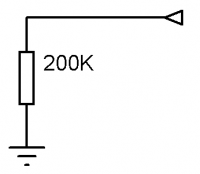
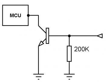
Electrically, channel neutral position - "air", is equivalent to a high resistance output, internally connected to the the GND terminal with resistor ~ 200k Ohm.
Digital output mode
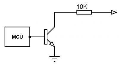
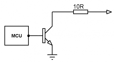
The channel configured to operate as a discrete output, sets at the appropriate controller pin, an electric potential, corresponding to the "ON" state, when writing a nonzero value to the address of channel output value register, and sets at the appropriate controller pin,an electric potential corresponding to the "OFF" state when recording the value of "0 " to the address of channel output value register.
Channel configuration for operation in this mode is determined by a constant, defining combination of parameters, that determine the electrical potential and current at the terminal of the corresponding controller channel in the "ON" and "OFF" position.
| Parameter | Acceptable values |
|---|---|
| Channel type | Digital output. |
| "ON" | plus (1mA); PLUS (100mA); minus (1mA); MINUS (100mA);air. |
| "OFF" | plus (1mA); PLUS (100mA); minus (1mA); MINUS (100mA);air. |
Named constants that represent channels configuration parameters combination available to the user, contains in the "DIO Channel Configuration" CannyLab constants directory, which can be accessed via function block entry context menu having a type of "constant".
To transfer controller channel in to digital output mode, it's necessary to copy the constant value corresponding to the selected mode in to corresponding channel address "Register channel configuration №**"
| Note: | For channels operating in the digital output configuration, it is also possible to obtain a value, corresponding to the actual current electrical potential at the channel terminal, which allows the use of channel feedback mode |
An example of a functional diagram performing every second, alternate switching of electrical potentials from + 12V (100mA) to GND (1 mA) at controller terminals, corresponding to channels #0 & #1.
PWM output mode
The channel configured for operation in PWM output, generates on the corresponding controller pin a pulse width signal of a predetermined polarity, frequency, and duty cycle. In this mode, the channel is asynchronous to functional diagram, which allows for greater stability of generated timing signal, than in the organization of PWM generator by functional diagram resources.
Channel configuration for operation in this mode is determined by a constant, representing a combination of parameters that determine the electrical potential and current to the terminal in the active "ON" and passive "OFF" generating phase, corresponding channel of the controller, and a pair of numeric values defining the frequency and filling generating pulses in milliseconds.
| Parameter | Acceptable values |
|---|---|
| Channel type | PWM output. |
| "ON" | plus (1mA); PLUS (100mA); minus (1mA); MINUS (100mA);air. |
| "OFF" | plus (1mA); PLUS (100mA); minus (1mA); MINUS (100mA);air. |
Named constants that represent channels configuration parameters combination available to the user, contains in the "DIO Channel Configuration" CannyLab constants directory, which can be accessed via function block entry context menu having a type of "constant".
To transfer controller channel in to PWM output mode it is necessary:
- to copy value constant, corresponding to the selected mode into selected channel address "DIO Mode IO Channel ##";
- to copy digital value 0 to 65565, setting generated pulses period in ms into selected channel address "DIO Period IO Channel ##" ;
- to copy digital value 0 to 65565, setting generated pulses duty cycle in ms into selected channel address "DIO Output IO Channel ##" ;
An example of a functional diagram performing every second, alternate switching of electrical potentials from + 12V (100mA) to GND (1 mA) at controller terminal, corresponding to channel #0.
Digital input mode
The channel, configured to operate as a digital input, returns a value of "1" in its input value register, if on the appropriate controller pin establishes an electrical potential corresponding to the "Input polarity" state; and returns the value "0" to input value register, if on the appropriate controller pin establishes an electrical potential not corresponding to the "Input polarity" state.
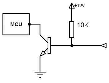
Channel configuration for operation in this mode is determined by a constant, representing a combination of parameters that determine the electrical potential at the terminal accepted for the state of "1" of corresponding controller channel, the existence and potential of internal controller pin "pull-up", sensitivity and channel activity in a low power mode of the controller.
| Parameter | Acceptable values |
|---|---|
| Channel type | Digital Input. |
| Input polarity | PLUS; MINUS. |
| Pull-up | plus; minus; air. |
| Standby mode | active; passive. |
| Sensitivity | max (0 ms); high (20 ms); norm (200 ms); low (700 ms). |
Change potential on the channel pin is in the active standby mode, will result in immediate automatic exip controller from hibernation. Change potential on the channel pin is in the passive standby mode, does not affect controller power consumption.
Channel sensitivity determines its "bounce protection", ie the time interval during which the electrical potential on the corresponding channel pin should remain unchanged, in order to be considered a set and change channel input value.
Named constants that represent channels configuration parameters combination available to the user, contains in the "DIO Channel Configuration" CannyLab constants directory, which can be accessed via function block entry context menu having a type of "constant".
To transfer controller channel into Digital Input mode it is necessary to copy value constant, corresponding to the selected mode into channel address "DIO Mode IO Channel ##".
An example of a functional diagram, switching-on a built-in green LED with the flow and hold for at least 200ms at the appropriate pin of channel №0, the potential GND:
Counter mode
The channel configured for operation of a counter, returns a number to its output value register, corresponding to the number of electric potential switching on the corresponding controller pin from the state opposite of the parameter "Input Polarity" into the state of the parameter "Input Polarity" for the last time a given duration. Thus, the channel in this mode functions as a counter of the signal rising edges or frequency meter.
In this mode, the channel is asynchronous to functional diagram, which allows for greater accuracy in determining the time parameters of the signal and measure higher frequency signal than in the organization of pulse counter by functional diagram resources.
Channel configuration for operation in this mode is determined by a constant, is parameters combination that determine the electrical potential when it appears at the controller channel corresponding pin registers the rising edge of a signal, presence and potential of internal "pull-up".
Channel Configuration for operation in this mode is given by the combination of the following parameters:
| Parameter | Acceptable values |
|---|---|
| Channel type | Input-Counter. |
| Input polarity | PLUS; MINUS. |
| Pull-up | plus; minus; air. |
In the counter mode, the channel is always in active standby with maximum sensitivity. Counting the number of state changes of this channel is carried out asynchronously.
Named constants that represent channels configuration parameters combination available to the user, contains in the "DIO Channel Configuration" CannyLab constants directory, which can be accessed via function block entry context menu having a type of "constant".
To transfer controller channel into Counter mode it is necessary:
- to copy value constant, corresponding to the selected mode into selected channel address "DIO Mode IO Channel ##";
- to copy digital value 0 to 65565, setting pulses counting period in ms into selected channel address "DIO Period IO Channel ##";
With a value of none-zero in the period register, the value in the input value register of a channel is updated once a period and contains the number of pulses registered by the counter in the intervening period.
Counting the pulse by the counter is conducted with overflow. This means that when the value of 65565 reached and subsequent increases by one, the counter value is set to zero, but each subsequent pulse again increments the counter by one.
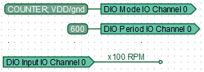
An example of a functional diagram of a tachometer with a resolution of 100 RPM, count the number of pulses on the controller pin corresponding to channel №0:
| Note: | If the period is set to zero, the counter continuously counts pulses with result accumulation in the register of the channel output value. In this mode, the value of this register is reset only by register overflow . |
Equivalent circuit diagrams
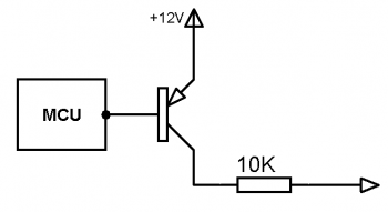
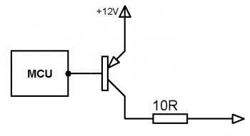
Equivalent circuit diagrams for each possible state of the input-output channel shown in the table below:
| Channel state | Equivalent circuit diagram |
|---|---|
| «air» | |
| «plus (1mA)» | |
| «PLUS (100mA)» | |
| «minus (1mA)» | |
| «MINUS (100mA)» | |
| «pull up air» | |
| «pull up plus» | |
| «pull up minus» |
Electrical protection
For channels operated in a digital output and PWM output modes, whose current in "ON" or "OFF" state significantly exceeds 100 mA, controller system software performs automatic short circuit protection. Protection implemented as the form of switching of a shorted channel into the neutral mode, the subsequent periodic pulse of start test and reset to a user-defined configuration upon detection elimination of short circuit. This protection is fully automatic and requires no user configuration.


