| This documentation is out of date.
The new version of the documentation is here: https://cannylogic.com/docs |
Difference between revisions of "CANNY 7, HR PWM Driver"
| [unchecked revision] | [unchecked revision] |
(→Drivers Registers) |
|||
| Line 23: | Line 23: | ||
!Expected Values | !Expected Values | ||
|- valign="top" | |- valign="top" | ||
| − | |style="padding-left:0.5em;"|HR PWM | + | |style="padding-left:0.5em;"|HR PWM 1 & 2 Period Register, μs |
|valign="top"| | |valign="top"| | ||
{|border="0" align="left" | {|border="0" align="left" | ||
| Line 35: | Line 35: | ||
{|border="0" align="left" | {|border="0" align="left" | ||
|- valign="top" | |- valign="top" | ||
| − | |style="padding-left:0.5em;"|HR PWM | + | |style="padding-left:0.5em;"|HR PWM 1 Enable Register |
|- valign="top" | |- valign="top" | ||
| − | |style="padding-left:0.5em;"|HR PWM | + | |style="padding-left:0.5em;"|HR PWM 2 Enable Register |
|} | |} | ||
| | | | ||
| Line 54: | Line 54: | ||
{|border="0" align="left" | {|border="0" align="left" | ||
|- valign="top" | |- valign="top" | ||
| − | |style="padding-left:0.5em;"|HR PWM | + | |style="padding-left:0.5em;"|HR PWM 1 Duty Register, μs |
|- valign="top" | |- valign="top" | ||
| − | |style="padding-left:0.5em;"|HR PWM | + | |style="padding-left:0.5em;"|HR PWM 2 Duty Register, μs |
|} | |} | ||
| | | | ||
| Line 69: | Line 69: | ||
{|border="0" align="left" | {|border="0" align="left" | ||
|- valign="top" | |- valign="top" | ||
| − | |style="padding-left:0.5em;"|HR PWM | + | |style="padding-left:0.5em;"|HR PWM 1 Pull-up Enable Register |
|- valign="top" | |- valign="top" | ||
| − | |style="padding-left:0.5em;"|HR PWM | + | |style="padding-left:0.5em;"|HR PWM 2 Pull-up Enable Register |
|} | |} | ||
| | | | ||
Revision as of 15:18, 11 September 2016
General description
Two of the twelve IO channels (Channels #1 and #2) CANNY 7 supports high-resolution pulse-width modulator mode. The channels may be activated independently of each other and have independent duty cycle and pull-up line configuration, however, the high resolution PWM period is a parameter common to both channels. In HR PWM mode, PWM timing - the period and duty cycle are set in the range from 2 to 20,000 microseconds, in increments of 1 microsecond.
In HR PWM, the channel has a fixed pulse polarity - GND 100mA. Generation can be conducted in either open collector - no pull-up lines or external, so as in internal pull-up mode to +12V (specified by setting the value in the appropriate register). In this mode, the channel is asynchronous to functional diagram, which allows for maximum timing stability of generated signal.
The driver of high resolution pulse width modulator (HR PWM) operates using Discrete Inputs and Outputs resources, wherein, having a higher priority. Thus, upon activation of the RR PWM driver, controller channels used by it are unavailable to input-output drivers.
| Note: | In high resolution pulse width modulator mode, the electrical protection from short circuit is disabled! Overload or channel short-circuit which are in high resolution PWM mode, can lead to controller failure! |
Drivers Registers
The following shows permissible values for control registers of high resolution PWM driver.
| Address | Expected Values | ||||||||
|---|---|---|---|---|---|---|---|---|---|
| HR PWM 1 & 2 Period Register, μs |
| ||||||||
|
| ||||||||
|
| ||||||||
|
|
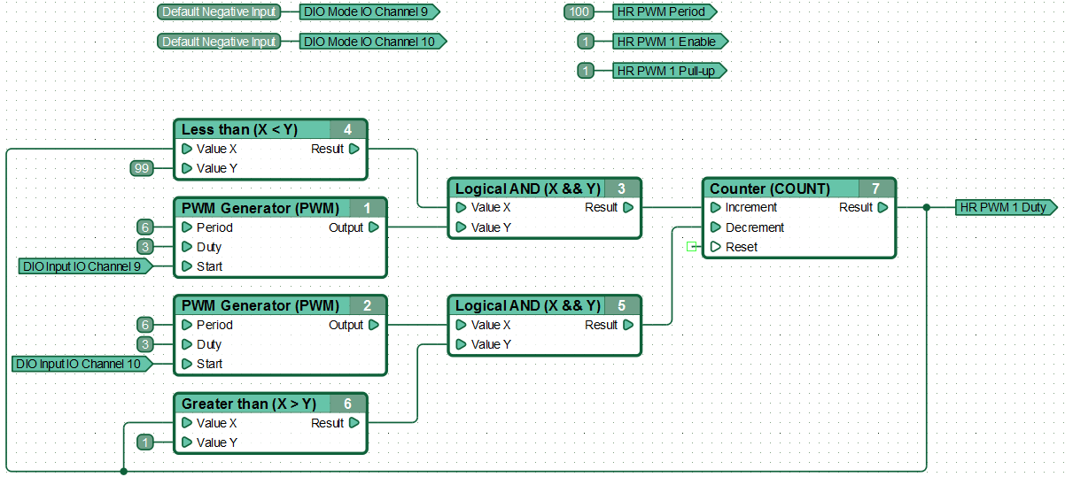
An example of a functional diagram, continuously adjustable HR PWM duty cycle with carrier frequency 10 kHz on channel #1, by pressing / holding the buttons connected to the channels #9 and #10:
