| This documentation is out of date.
The new version of the documentation is here: https://cannylogic.com/docs |
Difference between revisions of "CANNY 7, User Preprogrammed Parameters"
| [unchecked revision] | [unchecked revision] |
(→User Preprogrammed Parameters Registers) |
(→Пример использования параметров пользовательской конфигурации) |
||
| Line 40: | Line 40: | ||
|} | |} | ||
| − | === | + | === An example of using user configuration parameters === |
| − | + | Creating in CannyLab environment an executable stand-alone loading software, specified controller system software file and the file containing the diagram below, set two user parameters: Name «The duration of the output signal,ms», Type «Number» and Name «Controller output channel», Type «List». In the list of parameter values «Controller output channel» add two lines: Name «Cannel 0», Value «0» and «Cannel 1», Value «1». | |
[[File:6_14_3_1.png|center|1100px]] | [[File:6_14_3_1.png|center|1100px]] | ||
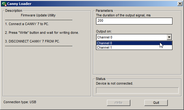
| − | + | Run created in this way the executable autonomous software loading file, set the required parameter values and write the software in the controller. | |
[[File:6_14_3_2.png|center]] | [[File:6_14_3_2.png|center]] | ||
| − | + | Performing the diagram, controller at the time of receiving negative potential on input channel #8, set on a user-defined in the corresponding parameter channel potential «GND» and keeps it user-specified time. For clarity, in the diagram is implemented indication of the output channel status by control LED. | |
== See also == | == See also == | ||
Revision as of 11:21, 24 July 2016
Contents
General description
The user preprogrammed parameters can be set by the end user during loading a software to the controller with Firmware Update Utility. After loading the software and launch the controller in stand-alone mode, the user-defined data become available to the functional diagramin in relevant controller registers.
Proper use of user parameters greatly increases the flexibility and versatility of the controller-based solutions, alloving the end user without expirience working with CannyLab, make safe changes in the operation of the controller algorithm using a simple user interface.
User Preprogrammed Parameters Registers
It is possible define up to 16 user parameters that will be available in the respective 16 controller registers.
| Address | Expected values | ||||||
|---|---|---|---|---|---|---|---|
|
|
The values in these registers will be established at the start of the controller, after loading software in to it, by the executable stand-alone loading file, and will remain unchanged (constant) throughout the entire period of the functional diagram operation, will not change even when the controller is reset. Change of register data values is possible only by overwriting or erasing controller memory with new software.
The values of the registers relevant to the parameters not listed in the standalone executable file is set to zero.
| Note: | When loading controller from SDE CannyLab, the values of all user configuration parameters registers set to zero. |
An example of using user configuration parameters
Creating in CannyLab environment an executable stand-alone loading software, specified controller system software file and the file containing the diagram below, set two user parameters: Name «The duration of the output signal,ms», Type «Number» and Name «Controller output channel», Type «List». In the list of parameter values «Controller output channel» add two lines: Name «Cannel 0», Value «0» and «Cannel 1», Value «1».
Run created in this way the executable autonomous software loading file, set the required parameter values and write the software in the controller.
Performing the diagram, controller at the time of receiving negative potential on input channel #8, set on a user-defined in the corresponding parameter channel potential «GND» and keeps it user-specified time. For clarity, in the diagram is implemented indication of the output channel status by control LED.

