| This documentation is out of date.
The new version of the documentation is here: https://cannylogic.com/docs |
CANNY Lab Simulator
CannyLab simulator mode performs actions with data of the diagram, equivalent to those to be executed by a controller computing kernel when running diagram on it, thus allowing simulation of the controller operation on a PC.
The user can run the simulation of executing the functional diagram for debugging and testing at any stage of its creation. Simulation mode enables cycling and stepping through diagram, setting the conditions to pause the execution, forced setting inputs and outputs values of function blocks, and control of intermediate values.
| Note: | In the current version of CannyLab simulator there is no support of controller hardware resources, so the reading results from addresses and write to the address in the simulator may differ from the results obtained in diagram execution by the controller. |
Contents
Enabling simulation mode
Enabling and disabling the simulation mode is done by selecting the appropriate item in the «Simulator» of main menu, or by pressing ![]() of toolbar.
of toolbar.
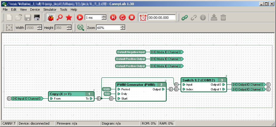
In simulation mode, the appearance of the main window and diagram changes - removed not available in this mode dialog elements, debugging information is added on the diagram.
When the simulation is activated, consistency diagram check, count memory (RAM) and program memory (ROM) that the controller required to run will be performed. The user will be warned about any issues. Functional blocks order of execution will be automatically detected and displayed. All intermediate values of inputs and outputs of functional blocks, blocks internal memory and the value of all the networks will be reset to 0, a pointer to the next block in the execution queue will be set to the first block of the diagram, setting simulation clocking to real time. The user can also freely move around the diagram and change scale, but editing diagram elements in simulator mode is restricted.
Continuous diagram execution
Running a continuous diagram execution by simulator is performed by selecting «Simulator» → «Start» of main menu or click the button ![]() toolbar, which in this case takes the following form
toolbar, which in this case takes the following form ![]() .
.
| Note: | The items "Start" and "Pause" of menu "Simulator" and buttons |
When binding simulator clock to real time ![]() , which is enabled by default in the simulation mode, the simulator clock
, which is enabled by default in the simulation mode, the simulator clock ![]() start the countdown looping diagram execution with a speed of PC system clock. If disable this binding, simulator internal clock will go as fast as possible, determined by the performance of the PC.
start the countdown looping diagram execution with a speed of PC system clock. If disable this binding, simulator internal clock will go as fast as possible, determined by the performance of the PC.
The scale of diagram time ![]() sets the increment that will be added to simulator clock after each pass of the diagram. This parameter can be seen as the time the controller takes to one full execute of users diagram.
sets the increment that will be added to simulator clock after each pass of the diagram. This parameter can be seen as the time the controller takes to one full execute of users diagram.
| Note: | To debug a large user diagrams, implementing critical runtime algorithms for PLC CANNY 7 time scale is recommended by setting the rate of 1 ms for every 30 function blocks. |
When changing the values of inputs and outputs of the functional blocks during the execution of the diagram, new values are displayed on diagram immediately beside them. For clarity, the network connected to the outputs of blocks having a value other than zero, will be highlighted.
Pause and reset
Pausing execution of diagram by simulator - select «Simulator» → «Pause» of main menu or click the button ![]() of toolbar, which in this case takes the following form
of toolbar, which in this case takes the following form ![]() .
.
A functional block in which diagram execution has been suspended, will be highlighted in yellow. Networks, with the values changed in the last step will also be highlighted, simulator clock will be stopped.
| Note: | The items "Start" and "Pause" of menu "Simulator" and buttons |
To enable auto-tracking option for the current diagram block, select «Simulator» → «Show block» of main menu or click the button ![]() of toolbar, display diagram in the workspace is shifted so that the working area contain a functional block on which execution was suspended.
of toolbar, display diagram in the workspace is shifted so that the working area contain a functional block on which execution was suspended.
Continuing diagram execution at a point where it was interrupted, by selecting «Simulator» → «Start» of main menu or click the button ![]() of toolbar.
of toolbar.
Fully stop diagram execution process and reset simulator to the initial state by selecting «Simulator» → «Reset» of main menu or click the button ![]() of toolbar.
of toolbar.
Conditional pausing
The simulator provides the ability to automatically pause the execution of the diagram on the following conditions:
- when any value on the diagram has changed;
- when the value of a particular network on the diagram has changed;
- after execution of the next functional block on the diagram (step mode);
- before the execution of a specific function block on the diagram;
- on completion of a full cycle of the diagram;
Enabling and disabling automatic suspension of execution for any data changes performed by selecting «Simulator» → «Watch Changes» of main menu or click the button ![]() of toolbar.
of toolbar.
Execution of the next function block, followed by suspension of diagram execution performed by selecting «Simulator» → «Next» of main menu or click the button ![]() of toolbar.
of toolbar.
Performing one full diagram cycle with the suspension of execution of the current function block performed by selecting «Simulator» → «Loop» of main menu or click the button ![]() of toolbar.
of toolbar.
Installing and removing a breakpoint on a particular functional block is performed by selecting the appropriate context menu item, available at the click of the right mouse button on the block. Background of the function block header declared breakpoint in simulator mode will be highlighted in red.
In the presence on the function block declared as breakpoint on the diagram, execution of the diagram will be suspended before each execution of each such block.
Installing and removing a breakpoint on a specific network is performed by selecting the appropriate context menu item, available at the click of the right mouse button on any network segment. The color of all segments of the network declared a breakpoint in simulator mode will be changed to red.
In the presence of networks on the diagram declared breakpoints, diagram execution is suspended each time the value of each such network has changed.
| Note: | Set or remove a breakpoint in the network or function block can be done also by double-clicking the left mouse button on these diagram elements. |
Forced change values
To simulate external influences on the diagram during simulation, the simulator provides the ability to manually forced change the current network values.
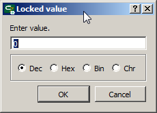
Forced change network values is done by selecting the context menu item «Lock Value» available by right-clicking on any network segment.
In the dialog box, opened after selecting this item, entering forcibly setting value.
Value forcibly set for the network, displayed as a label on a black background.
Assigned forced value of the network will be used by functional blocks connected to this network, instead of its real value until released manually.
Return the network to obtain the values determined by diagram operation is performed by selecting the context menu item «Unlock Value» available by right-clicking on any network segment with forcing set value.
Quickly force the value of a network equal to one, or a quick release the network value can also be a by double-clicking the left mouse button on the network, holding down the «Ctrl» button.
Changing numeral system of displayed values
By default, all values are displayed in the simulator as a decimal. However, the value numeral system can be changed at any time, such as hexadecimal, selecting the appropriate submenu item «Simulator» → «Values Format» of main menu.


