General Description
Using the CAN gateway driver you can to implement the high-speed asynchronous relaying of messages between the CAN hardware interfaces with optional filtering and altering particular CAN messages.
The CAN gateway driver allows you to realize individual processing of incoming CAN messages by configuring up to eight selection rules (selectors).
Each rule (selector) allows you to select CAN messages by the combination of following user-defined properties values:
- CAN interface number via which the message was coming to the controller;
- CAN ID of incoming message (CAN gateway selector value).
When some incoming CAN message hit the selector, the CAN gateway driver perform one of the following user-defined actions:
- relay the message to another CAN interface of the controller "as is", without any changes;
- modify the message, and then relay the modified message to another CAN interface of the controller;
- discard the message.
In case of the message modification it is performed by replacing using a bitmask any bits of the original message. You can change any CAN-message field including ID, length and bits of data.
For all incoming CAN message that are not hit in any selector, you can assign one of the following actions:
- relay the message to another CAN interface of the controller "as is", without any changes;
- discard the message.
To use the CAN gateway driver, it is necessary to specify the possible different configurations for both CAN-interfaces of the controller.
When the CAN gateway driver is enabled, the diagram still can use the registers of the CAN0 Driver and the CAN1 Driver for:
- sending any CAN messages through any of the CAN interfaces;
- receive CAN messages, but only those that are hit some CAN gateway driver selector, regardless of what happens with the CAN message after its selection.
Moreover, you can change CAN gateway driver configuration during operation. So you can organize some sort of the dynamic mode for your CAN gateway.
Driver's registers
Below is a description of the permissible values of the CAN gate driver control registers, which allow setting the controller operation parameters for high-speed asynchronous relaying of messages between the CAN hardware interfaces.
Common registers of the CAN gateway driver.
| Register
|
Expected values
|
| CAN Gateway Driver Enable Register
|
|
| ≥ 1
|
=
|
Enable the CAN Gateway Driver;
|
| = 0
|
=
|
Disable the CAN Gateway Driver.
|
|
| CAN Gateway Configuration Update Register
|
|
| ≥ 1
|
=
|
Apply the new settings of the CAN gateway driver. Must be shortly set when the CAN Gateway Driver parameters need be changed during operation;
|
| = 0
|
=
|
Do not update the settings of the CAN gateway driver.
|
|
| CAN Gateway Filtering Mode on CAN interface X
|
|
| ≥ 1
|
=
|
switch on the filtering mode of the CAN gateway for the corresponding interface: relay to the second CAN interface of the controller and transmit only CAN messages that are accepted by the gateway selections, the remaining messages are discarded;
|
| = 0
|
=
|
the filtering mode of the CAN gateway for the corresponding interface is disabled: it automatically retransmits messages that have not entered the gateway selections to the second CAN-interface of the controller in unchanged form.
|
|
| CAN Gateway Tracing Mode on CAN interface X
|
|
| ≥ 1
|
=
|
enable the CAN gateway tracing mode for the corresponding interface: transmit to the function chart (in the CAN driver) all CAN messages received on this interface. The gateway driver will select, replace and relay CAN messages according to the corresponding gateway settings of the specified CAN interface;
|
| = 0
|
=
|
disable the CAN gateway tracing mode for the corresponding interface: only CAN messages that are included in the gateway's selections are transmitted to the diagram (in the CAN driver), the remaining messages are discarded.
|
|
Common diagnostic registers of the CAN gateway driver.
| Register
|
Return values
|
| CAN Gateway Overflow Register
|
|
| 1
|
=
|
error, CAN Gateway Driver overflow occurred (see note);
|
| 0
|
=
|
CAN Gateway Driver overflow is missing, the Driver is operating normally.
|
|
| CAN Gateway CANx Interface Selector Hit Register
|
|
| 0...17
|
=
|
selectior number to which the current (actual) received CAN message of the corresponding interface corresponds.
|
|
| Note:
|
The occurrence of an overflow error in the CAN Gateway Driver means that at the time a new CAN message arrived, the previous message from the same selection was not picked up and processed, the previous message was overwritten with a newer one, data loss occurred.
|
Common CAN Gateway Driver selection registers.
| Registers
|
Expected values
|
| CAN Gateway Selector X Enable Register
|
|
| ≥ 1
|
=
|
enable the appropriate selection of the CAN gateway;
|
| = 0
|
=
|
the corresponding CAN gateway selection is disabled.
|
|
| CANGW Selector X Linked CAN Interface Number Register
|
|
| = 0
|
=
|
apply the appropriate selection to the messages coming to the controller via the CAN0 interface;
|
| = 1
|
=
|
apply the appropriate selection to the messages coming to the controller via the CAN1 interface.
|
|
| CAN Gateway Selector X Drop Mode Enable Register
|
|
| ≥ 1
|
=
|
discard all messages which match an enabled selection;
|
| = 0
|
=
|
allow processing and automatic retransmission to another CAN interface of all messages which match an enabled selection.
|
|
| CAN Gateway Selector X Disable Tracing Register
|
|
| ≥ 1
|
=
|
disable the transfer of the corresponding selection data to the CAN driver registers, make the selection messages inaccessible in the user diagram;
|
| = 0
|
=
|
enable the transfer of the corresponding selection data to the CAN driver registers, make the selection messages accessible in the user diagram.
|
|
CAN Gateway Driver selection registers.
The value of the selection - is a parameter which, when satisfied, selects an incoming CAN message for special processing.
| Register
|
Expected value
|
| CAN Gateway Selector X Value Setup Register, CAN IDL
|
|
| 0...0xFFFF
|
=
|
the value of the lower part of the identifier (bits 0 ... 10 of the standard format identifier or bits 0 ... 15 of the extended format identifier) of the CAN message the selection will accept.
|
|
| CAN Gateway Selector X Value Setup Register, CAN IDH
|
|
| 0...0x1FFF
|
=
|
the value of the highest part of the identifier (bits 16 ... 28 of the extended format identifier) of the CAN message the selection will accept.
|
|
| CAN Gateway Selector X Value Setup Register, CAN ERL
|
|
| 0...0xXX08
|
=
|
a value equal to the number of data bytes in the received CAN message of the corresponding interface, where 0xXX is: 0x00 (with standard format), 0x40 (with standard format with RTR), 0x80 (with extended format) or 0xС0 (with extended format with RTR) (See note).
|
|
| CAN Gateway Selector X Value Setup Register, CAN D1:D0
|
| ...
|
| CAN Gateway Selector X Value Setup Register, CAN D7:D6
|
|
| 0...0xFFFF
|
=
|
values of bytes (bit) of CAN-message data, according to which a check is made for compliance of the message with this selection.
|
|
| Note:
|
CAN Received Data Register ERL, in addition to the number of bytes in the received message 0 ... 8 least significant bits, contains in its most significant bits information about special message attributes: bit 15 - EXT sign & bit 14 - RTR sign. Where EXT = 1, when receive a message in the extended format, EXT = 0 for a standard message format; RTR = 1 when receiving remote data request, EXT = 0 when receiving normal message.
|
The registers of the Gateway Driver selection masks.
The selection masks - is a group of values whose bits define the bitwise modifications to be made when the gateway retransmits a part of the message that has been accepted by the appropriate selection. If the value of the mask bit is "0", the corresponding bit of the received message will be relayed to the other interface without changes. If the value of the mask bit is "1", the corresponding bit of the received message will be replaced by a corresponding bit from the value of the appropriate Replace Setup Register,
| Register
|
Expected value
|
| CAN Gateway Selector X Mask Setup Register, CAN IDL
|
|
| 0...0xFFFF
|
=
|
set the value of the mask of the lower part of the CAN message identifier (bits 0 ... 10 of the standard format identifier or bits 0 ... 15 of the extended format identifier) of the corresponding selection.
|
|
| CAN Gateway Selector X Mask Setup Register, CAN IDH
|
|
| 0...0x1FFF
|
=
|
set the mask value of the upper part of the CAN message identifier (bits 16 ... 28 of the extended format identifier) of the appropriate selection.
|
|
| CAN Gateway Selector X Mask Setup Register, CAN ERL
|
|
| 0...0xFFFF
|
=
|
Set the mask value of the ERL register of the CAN message of the appropriate selection.
|
|
| CAN Gateway Selector X Mask Setup Register, CAN D1:D0
|
| ...
|
| CAN Gateway Selector X Mask Setup Register, CAN D7:D6
|
|
| 0...0xFFFF
|
=
|
set the value of the mask for the corresponding byte of data of the CAN message of the corresponding selection.
|
|
Registers for replacing the selections of the CAN Gateway Driver.
Replacement of selection - is a group of values whose bits replace the original bits in the retransmitted message that has fallen into the appropriate selection. If the value of the replacement bit is "0", the corresponding bit of the relayed message will be replaced by zero, with the replacement bit value equal to "1", the corresponding bit of the relayed message will be replaced by one. The replacement will only be applied to those bits whose selection mask value is "1".
| Register
|
Expected value
|
| CAN Gateway Selector X Replace Setup Register, CAN IDL
|
|
| 0...0xFFFF
|
=
|
set the value of the replacement of the lower part of the CAN message identifier (bits 0 ... 10 of the standard format identifier or bits 0 ... 15 of the extended format identifier) of the corresponding selection.
|
|
| CAN Gateway Selector X Replace Setup Register, CAN IDH
|
|
| 0...0x1FFF
|
=
|
set the value of the replacement of the highest part of the CAN message identifier (bits 16 ... 28 of the extended format identifier) of the corresponding selection.
|
|
| CAN Gateway Selector X Replace Setup Register, CAN ERL
|
|
| 0...0xFFFF
|
=
|
set the replacement value of the ERL register of the CAN message of the selection being used.
|
|
| CAN Gateway Selector X Replace Setup Register, CAN D1:D0
|
| ...
|
| CAN Gateway Selector X Replace Setup Register, CAN D7:D6
|
|
| 0...0xFFFF
|
=
|
set the replacement values of the corresponding data bytes of the CAN message of the corresponding selection.
|
|
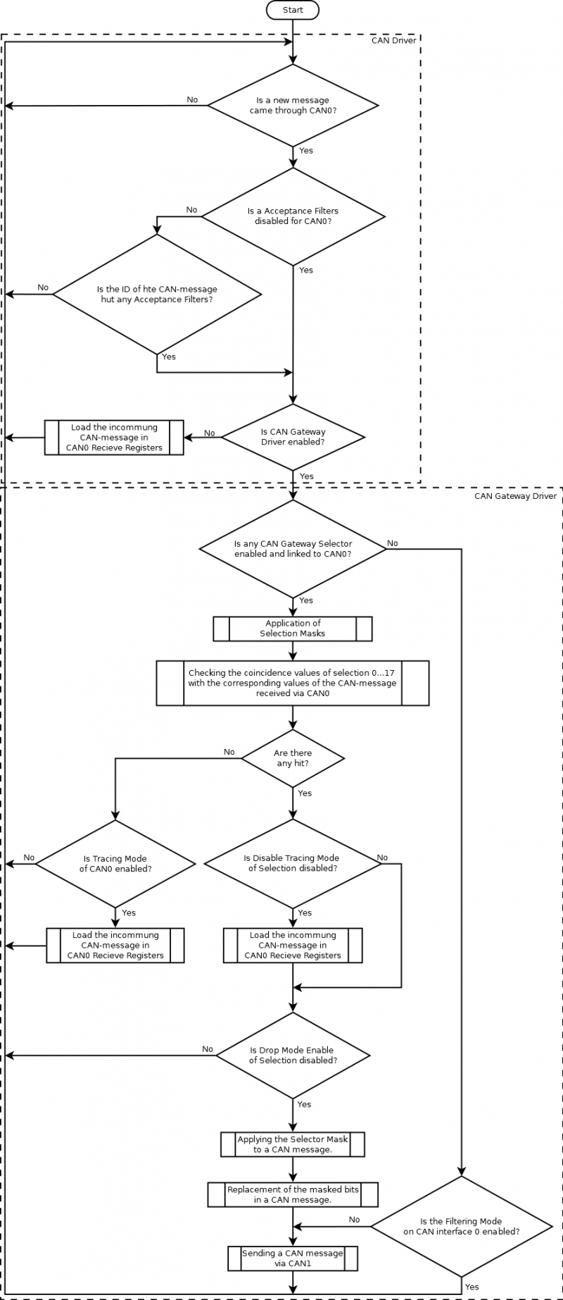
Diagram of the CAN Gateway Driver operation
The block diagram shows the processing of CAN messages received through CAN0 interface. CAN messages received through CAN1 are processed in a similar manner.
Examples
Example 1: Disable the retransmission of CAN messages with the specified identifier.
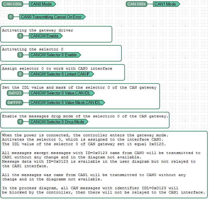
All messages, except messages with ID = 0x0123, that came from CAN0 are transmitted to CAN without any changes and are not included in the diagram. Message data with ID = 0x0123 may be available in the user diagram, but not relayed to the CAN1 interface.
All messages coming from CAN1 are transmitted to CAN0 without changes, they are not included in the diagram.
Example 2: Static Gateway: CAN message relay with data change.
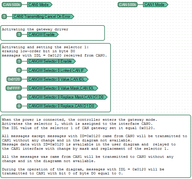
All messages, except messages with ID = 0x0120, that came with CAN0 are transmitted to CAN1 without any changes and are not included in the diagram. Data messages with ID = 0x0120 can be available in the user diagram and are relayed to the CAN1 interface with the given mask and replacement selection.
All messages coming from CAN1 are transmitted to CAN0 without changes, they are not included in the diagram.
In the process of operation, the message diagrams with IDL = 0x0120 will be transmitted to CAN1 with a bit of 0 byte D0 equal to 0.
Example 3: Processing received CAN messages in a custom diagram.
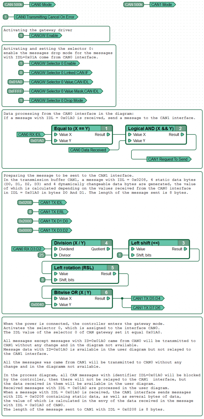
All messages, except messages with ID = 0x01A0, that come from the CAN0 interface are transmitted to CAN1 without any changes and are not included in the diagram. Message data with ID = 0x01A0 may be available in the user diagram, but not relayed to the CAN1 interface.
All messages coming from CAN1 are transmitted to CAN0 without changes, they are not included in the diagram.
In the course of the diagram operation, all CAN messages from the CAN0 interface with IDL = 0x01A0 will be blocked by the controller, i.e. will not be relayed to the CAN1 interface, but the data received from them will be available in the custom diagram.
Received messages with IDL = 0x01A0 are processed in the user diagram. When a message with IDL = 0x01A0 is received at the CAN1 interface, a message with IDL = 0x0208 containing static data is sent, as well as several data bytes, the value of which is calculated depending on the data received in the message IDL = 0x01A0 from CAN0. The length of the message sent to CAN1 with IDL = 0x0208 is 8 bytes.
Example 4: Dynamic gateway.
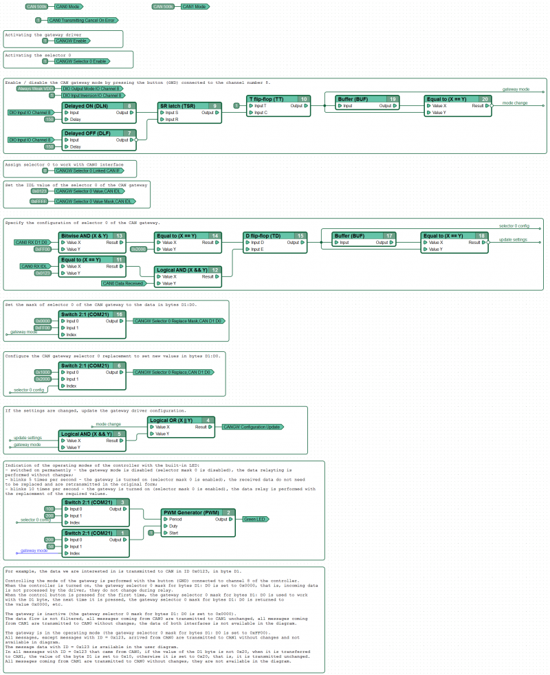
For example, the data of interest to us is transmitted to CAN in ID 0x0123, in byte D1.
The mode of operation of the gateway is controlled using a clock button (GND) connected to channel No. 8 of the controller. When the controller is turned on, the selection screen 0 of the gateway D1:D0 is set to 0x0000, i.e. the incoming data is not processed by the driver, there is no change in them during retransmission. The first pressing of the control button sets the selection mask 0 of the gateway D1:D0 to work with byte D1; the next time it is pressed, the selection mask 0 of the gateway D1:D0 returns to the value 0x0000, etc.
Gateway is inactive (selection screen 0 of gateway D1:D0 is set to 0x0000). Data stream filtration is not performed, all messages that came from CAN0 are transmitted to CAN1 without changes, all messages that came from CAN1 are transmitted to CAN0 without changes, the data of both interfaces are not included in the diagram.
The gateway is in operation (selection screen 0 of the gateway D1:D0 is set to 0xFF00).
All messages, except messages with ID = 0x123, that came from CAN0 are transmitted to CAN1 without any changes and are not included in the diagram. Message data with ID = 0x123 is available in the custom diagram. In all messages with ID = 0x123, sent from CAN0, if the value of byte D1 is not equal to 0x20, when transmitting them to CAN1, the value of byte D1 is set equal to 0x10, otherwise - it is set equal to 0x20, i.e. transmitted without change.
All messages coming from CAN1 are transmitted to CAN0 without changes, they are not included in the diagram.
ATTENTION! Any change in the settings of the gateway (for example, selection mask registers or selection replacement registers) requires updating the driver configuration using a special register.
See also
CANNY 7.2 duo
CANNY 7.2 duo, CAN Driver


