General Description
Controllers CANNY 5.2 duo have two independent CAN interfaces. Two special external contact Canny controller 5.2 duo, located on the 4-pin connector X1 (CAN0-H and CAN0-L of CAN0 interface) and the contacts on the 2-pin connector X3 (CAN1-H and CAN1-L of CAN1 interface), provided for connection to digital information CAN-buses.
A feature of the driver CAN controller CANNY 5.2 duo is that the number of filters CAN0 interface is equal to 8 (compared to 16 in CANNY 7). CAN1 interface have only 4 filters.
Interfaces CAN0 and CAN1 have individual settings and can operate at different speeds of data exchange that allows you to connect CANNY 5.2 duo controller simultaneously to two different CAN buses.
Driver's registers
Below is a description of valid values for registers controlling CAN-bus driver operation, where x is a CAN interface number (0 or 1).
CAN driver configuration registers allows to set the parameters of the controller as a CAN bus node for the used CAN interface:
| Address
|
Expected values
|
|
|
| 1...N
|
=
|
driver activation and CAN-messages transmit/receive speed setting for the used CAN interface (defined by a special constant of constants directory);
|
| 0
|
=
|
driver disabled.
|
|
| CANx Acceptance Filter Identifier Register IDL 0
|
| ...
|
| CANx Acceptance Filter Identifier Register IDL 7
|
|
| 0...0xFFFF
|
=
|
set filter value for lower part of CAN-message identifier(bits 0...10 identifier standard format or bits 0...15 expanded identifier format);
|
|
| CANx Acceptance Filter Identifier Register IDH 0
|
| ...
|
| CANx Acceptance Filter Identifier Register IDH 7
|
|
| 0...0x1FFF
|
=
|
set filter value for higher part of CAN-message identifier (bits 16...28 expanded identifier format);
|
|
| CANx Listen Only Mode Enable Register
|
|
| ≥ 1
|
=
|
CAN messages passive reception mode for the used CAN interface enabled (listen only);
|
| 0
|
=
|
CAN messages reception and transmission mode for the used CAN interface enabled (normal);
|
|
| CANx Acceptance Filter Enable Register
|
|
| ≥ 1
|
=
|
CAN received messages filtering mode for the used CAN interface enabled;
|
| 0
|
=
|
CAN received messages filtering mode for the used CAN interface disabled;
|
|
| CANx Transmitting Cancel On Error Register
|
|
| ≥ 1
|
=
|
CAN transmitting cancel on error for CAN0 interface is enabled, for CAN1 interface is always enabled;
|
| 0
|
=
|
CAN transmitting cancel on error for CAN0 interface is disabled.
|
|
| Note:
|
In passive receiving CAN messages mode (listen only), unlike normal CAN mode, the driver operates to receive data from CAN-bus, but does not send a confirmation of reception and does not puts network in an error state when it detects such. Thus, the controller remains invisible to the other devices on the bus, does not prove itself. For normal network operation, there must be present at least two devices operating in the normal mode.
|
| Note:
|
When filter mode enabled the CAN driver will accept only those messages whose identifiers match values in CAN message receive filter installation registers, ignoring all others.
|
CANx driver configuration is defined by a constant predetermined data transmission/reception speed.
| Parameter
|
A list of acceptable values
|
| Data transmission/reception speed, Kbit/s
|
10; 33; 50; 83; 95.2; 100; 125; 250; 500; 1000
|
Named constants that represent CAN configuration parameters combination, available to the user in the "CANx Modes" CannyLab constants directory, which can be accessed via function block entry context menu having "constant" type.
CAN driver diagnostics registers allows the user to determine the status of the driver in one or another moment of a diagram execution.
| Address
|
Returning Values
|
|
|
| 1
|
=
|
CAN driver activity of the used interface is absent, the bus is idle, the data reception is not performed;
|
| 0
|
=
|
CAN activity of the used interface registered.
|
|
|
|
| 1
|
=
|
error, CAN buffer of the used interface is full;
|
| 0
|
=
|
no overflow of the used interface receive buffer.
|
|
|
|
| 1
|
=
|
CAN reception error rate of the used interface exceeds a threshold;
|
| 0
|
=
|
CAN reception error rate of the used interface below an acceptable threshold.
|
|
| CANx Ready To Send Register
|
|
| 1
|
=
|
CAN driver data transmit buffer of the used interface is empty and ready to send new messages;
|
| 0
|
=
|
CAN driver data transmit buffer of the used interface is not ready.
|
|
CAN driver receiving registers allows access to the values obtained on the bus.
| Address
|
Return values
|
| CANx Data Set Ready Register
|
|
| 1
|
=
|
CAN driver receive buffer of the used interface has received message, this value appears in the register for one cycle of diagram execution, stating the relevance of data stored in the receive buffer;
|
| 0
|
=
|
there is no data in the CAN driver receive buffer of the used interface.
|
|
| CANx Received Data Register IDL
|
|
| 0...0xFFFF
|
=
|
the value of the lower part of the identifier received CAN-message of the used interface.
|
|
| CANx Received Data Register IDH
|
|
| 0...0x1FFF
|
=
|
the value of the higher part of the identifier received CAN-message of the used interface.
|
|
| CANx Received Data Register ERL
|
|
| 0...0xC000
|
=
|
a value equal to the number of bytes of data in the received message of the used interface, signs EXT and RTR (See note).
|
|
| CANx Received Data Register D1:D0
|
| ...
|
| CANx Received Data Register D7:D6
|
|
| 0...0xFFFF
|
=
|
values of the corresponding data bytes received in CAN message of the used interface, two bytes per register.
|
|
| Note:
|
CAN Received Data Register ERL, in addition to the number of bytes in the received message 0 ... 8 least significant bits, contains in its most significant bits information about special message attributes: bit 15 - EXT sign & bit 14 - RTR sign. Where EXT = 1, when receive a message in the extended format, EXT = 0 for a standard message format; RTR = 1 when receiving remote data request, EXT = 0 when receiving normal message.
|
CAN transmit registers are used to accommodate data in the transmission buffer to be sent.
| Address
|
Expected values
|
| CANx Request To Send Register
|
|
| ≥ 1
|
=
|
load data from the transfer registers in to CAN driver send buffer of the used interface;
|
| 0
|
=
|
do not load data to CAN driver transmission buffer of the used interface.
|
|
| CANx Transmit Data Register IDL
|
|
| 0...0xFFFF
|
=
|
the value of the lower part of the identifier transmitting CAN-message of the used interface.
|
|
| CANx Transmit Data Register IDH
|
|
| 0...0x1FFF
|
=
|
the value of the higher part of the identifier transmitting CAN-message of the used interface.
|
|
| CANx Transmit Data Register ERL
|
|
| 0...0xC000
|
=
|
the value equal to the number of bytes of data in the transmitted message of the used interface, signs EXT и RTR (see note).
|
|
| CANx Transmit Data Register D1:D0
|
| ...
|
| CANx Transmit Data Register D7:D6
|
|
| 0...0xFFFF
|
|
values of the corresponding data byte of transmitting CAN message of the used interface, two bytes per register.
|
|
| Note:
|
CAN Transmit Data Register ERL, in addition to the number of bytes in the transmitting message 0 ... 8 least significant bits, contains in its most significant bits information about special message attributes: bit 15 - EXT sign & bit 14 - RTR sign. Where EXT = 1, when transmitting a message in the extended format, EXT = 0 for a standard message format; RTR = 1 when transmitting remote data request, EXT = 0 when receiving normal message.
|
Examples
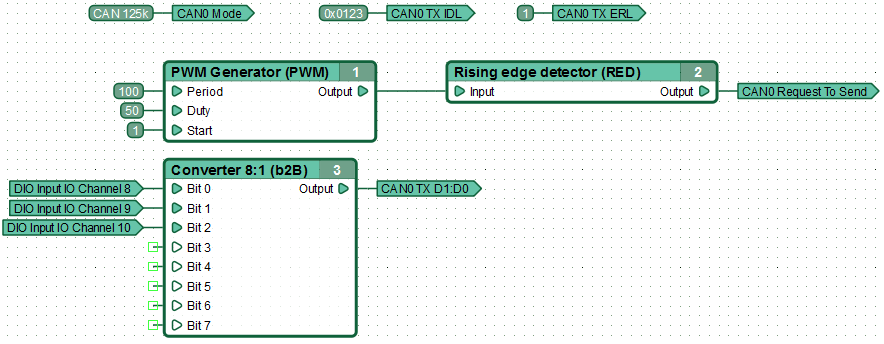
An example of a functional diagram of the data sent to the CAN bus via interface CAN0. Performing diagram the controller once every 100 ms, transmits to the bus at a speed of 125 kbps, the data about the state of its three inputs, using a standard format message with the identifier 0x123, contains a single byte of data.
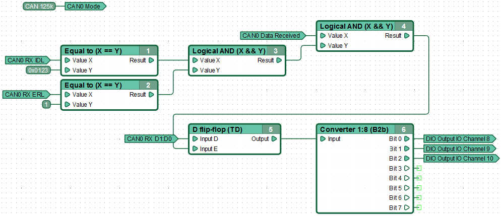
An example of a functional diagram of the data receive from the CAN bus via interface CAN0. Performing the diagram controller, receiving message from the bus in standard format with ID 0x0123, containing one byte of data, sets on three of its outputs, states in accordance with received value.
See also
CANNY 5.2 duo

